To match power adapter specifications, you must systematically align the output voltage of the adapter with the input voltage of your device, ensure the adapter’s current capacity equals or exceeds the device’s maximum load, and verify that both the connector physical profile and polarity are perfectly compatible. For many procurement managers and hardware design engineers, finding the exact power match is a frequent bottleneck that threatens project deadlines. A single specification mismatch can delay production runs, trigger unexpected board-level failures, or lead to catastrophic field returns. By taking a rigorous, step-by-step approach to evaluating power adapter specifications , you can eliminate system integration risks, improve energy conversion efficiency, and protect your brand’s operational integrity.
What Are Power Adapter Specifications?
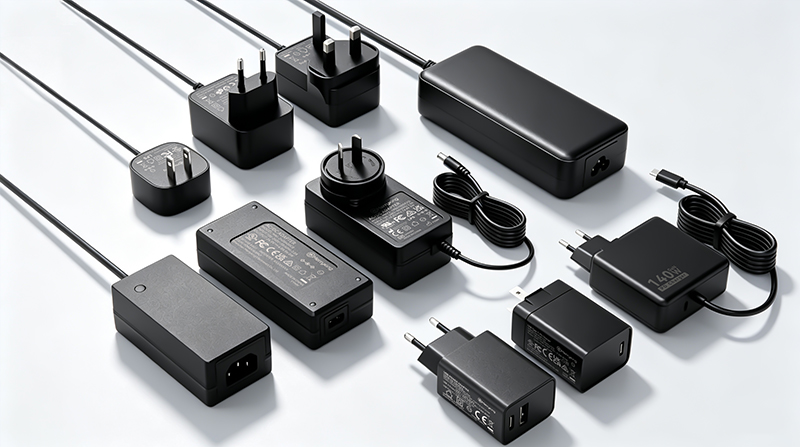
Power adapter specifications are the defined electrical and physical characteristics—including voltage, current, polarity, and connector dimensions—that govern how a power supply converts and delivers electrical energy to a device. Understanding these power adapter specifications is the first step toward achieving safe, reliable hardware operations.
What Are the Key Electrical Metrics?
Electrical metrics define the boundaries of power transmission and energy conversion safety. These parameters dictate how much power the adapter pulls from the wall source and how cleanly it delivers that power down to the device’s mainboard.
Look at it this way:
- Input Voltage and Frequency: The AC mains window (e.g., 100–240V, 50/60Hz) the adapter safely accepts.
- Output Voltage (V): The steady-state DC potential difference supplied to the load.
- Output Current (A): The maximum continuous electrical flow rate available to the system.
Selecting an adapter with mismatched electrical ratings will immediately degrade hardware performance or trigger over-voltage shutoffs. Engineers must verify both the nominal values and allowable tolerances before approving an adapter for mass distribution.
Which Physical Attributes Must You Check?
Physical attributes dictate whether a power supply can actually form a secure connection with your hardware. If the physical connection is weak, the electrical metrics of the adapter become completely irrelevant.
Here is the kicker:
- Connector Form Factor: The specific geometry of the plug, such as a cylindrical barrel or a standardized USB-C interface.
- Physical Dimensions: Exact physical measurements of the connector, including outer diameter (OD) and inner diameter (ID).
- Enclosure Styling: The structural design of the power block, categorizing units into wall-mount configurations or desktop brick styles.
The correlation between physical interface compatibility and steady electrical flow highlights why form factor cannot be ignored. Key Takeaway: Verifying both electrical boundaries and exact connector dimensions guarantees your device runs reliably without physical port damage or electrical hazard risks.
| Attribute | Parameter Type | Core Engineering Purpose | |
|---|---|---|---|
| Voltage / Current | Electrical | Determines safe power delivery and circuit compatibility | |
| Connector Size | Physical | Establishes a secure connection without signal interruption | |
| Pin Layout | Physical | Prevents incorrect electrical routing and reverse paths |
Analyze both physical and electrical traits in parallel to achieve a seamless power match.
Why Do Power Adapter Specifications Matter for Device Safety?
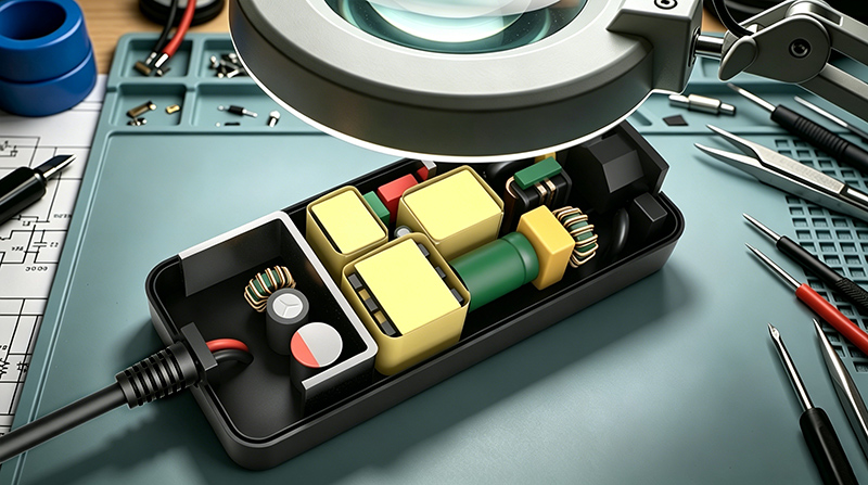
Device safety hinges directly on power adapter specifications because mismatched electrical parameters can cause thermal runaway, electrical fires, or catastrophic component breakdown. Evaluating power adapter specifications ensures your hardware operates within its designed safety boundaries without risking user harm.
How Do Mismatches Cause Thermal Failures?
Thermal failures occur when an adapter forces too much voltage through a circuit or when a device tries to pull more current than an adapter can safely handle. The resulting excess energy is released entirely as heat, melting plastic enclosures and compromising safety.
Think about it:
- Component Overheating: Delicate surface-mount components quickly exceed their maximum operating temperatures.
- Insulation Breakdown: High temperatures melt internal wiring insulation, causing catastrophic short circuits.
- Capacitor Failure: Electrolytic capacitors dry up or explode when exposed to prolonged thermal stress.
Protecting your product line means sourcing power systems built with robust over-temperature controls. Managing thermal safety at the adapter level keeps your end-user environment completely safe.
What Are the Long-Term Reliability Risks?
Using an adapter that is slightly out of spec might not destroy a device instantly, but it will slowly wear down internal protective circuits over time. This slow degradation results in premature product failures just after the warranty period expires.
What does this mean?
- Accelerated Semiconductor Aging: Continuous micro-stress on silicon gates decreases overall microchip lifespan.
- Voltage Regulator Degradation: Internal step-down converters must work harder, causing them to burn out early.
- Solder Joint Fatigue: Repeated, rapid temperature swings expand and contract boards until joints crack.
Operating outside designated parameters compromises safety margins and dramatically shortens product lifespan. Key Takeaway: Prioritizing built-in circuit protection shields your hardware from catastrophic thermal failures and guarantees consistent, long-term operational durability.
| Mismatch Type | Primary Thermal Consequence | Long-Term Reliability Risk | |
|---|---|---|---|
| Excessive Voltage | Rapid temperature spike and component melting | Permanent semiconductor gate destruction | |
| Insufficient Current | Overloaded power supply and voltage sagging | Repeated brownouts and premature regulator wear | |
| High Ripple Noise | Localized heating on filtering capacitors | Dried-out capacitors and system instability |
Rigorous safety planning prevents early field failures and reduces product liability.
How Do You Match Voltage in Power Adapter Specifications?
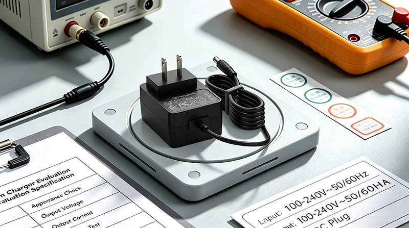
To match voltage in power adapter specifications, you must ensure the adapter’s output voltage precisely matches the input voltage rating required by the device. Selecting correct power adapter specifications means never deviating from this designated voltage level, as even minor variances can destroy circuits or prevent startup.
Why Is Exact Voltage Matching Mandatory?
Voltage represents the electrical pressure pushed into a device. If the pressure is too high, internal safety gates will blow; if the pressure is too low, the device will fail to power on.
Here is the deal:
- Over-Voltage Destruction: High voltage pierces semiconductor junctions, causing permanent, unrepairable hardware shorts.
- Under-Voltage Brownouts: Insufficient voltage prevents internal power-delivery paths from starting up.
- Regulator Overloading: Device step-down regulators must drop excess voltage, converting it into harmful waste heat.
Maintaining a perfectly matched voltage keeps your device operating within its optimal efficiency sweet spot.
Can Devices Tolerate Small Voltage Variances?
While some industrial designs include wide-input voltage tolerance circuits, standard B2B devices rely on precise, tight voltage parameters. Assuming your hardware can handle voltage fluctuations is a dangerous design gamble.
Let’s dig deeper:
- Standard Tolerance Windows: Most commercial electronic devices only allow for a small +/- 5% voltage variation.
- Line Regulation Drops: Budget adapters can drop output voltage significantly when under heavy loads.
- Line Noise Spikes: Unstable voltage regulation can inject destructive voltage spikes straight into your main processors.
Standardized tolerances must be treated as emergency margins rather than operational targets. Key Takeaway: Restricting voltage variance to +/- 5% ensures your sensitive processors remain protected against damaging voltage surges and unexpected brownouts.
| Rated Input | Safe Operational Window | Potential Fault Condition | |
|---|---|---|---|
| 5.0 V | 4.75 V to 5.25 V | Logic errors (lower limit) or fried gates (upper limit) | |
| 12.0 V | 11.40 V to 12.60 V | Drive failures (lower limit) or capacitor shorts (upper limit) | |
| 24.0 V | 22.80 V to 25.20 V | Controller resets (lower limit) or relay burnouts (upper limit) |
Always specify exact voltage matches to prevent unstable performance and safeguard sensitive internal regulators.
What Current Rating Should Power Adapter Specifications Include?
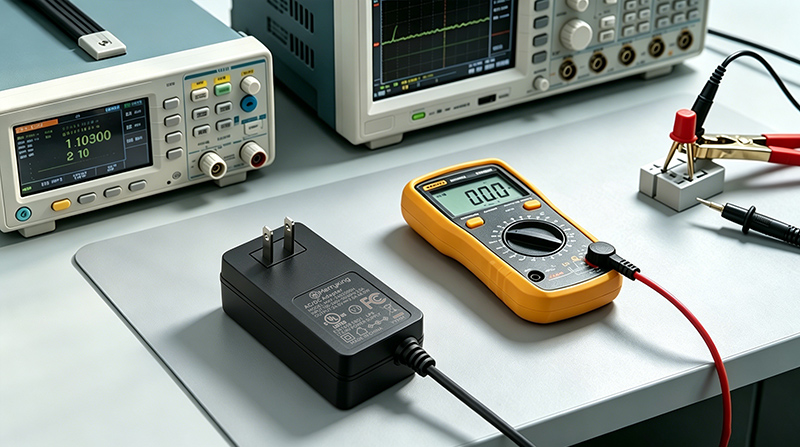
Power adapter specifications should include a current rating that is equal to or greater than the maximum current drawn by the device under full load. Selecting power adapter specifications with a higher current capacity is completely safe because the device will only pull what it needs.
Why Is ‘Equal to or Greater’ the Golden Rule?
Electrical current is pulled dynamically by the device, not pushed by the power supply. Sourcing an adapter with a larger amperage capacity simply provides a larger, safer reservoir of energy.
In other words:
- Demand-Driven Draw: The device only draws the exact amperage required to run its active systems.
- Reduced Stress on Adapter: Adapters operating below their maximum current limit run much cooler.
- Future-Proof Headroom: Extra amperage headroom allows for future device upgrades, such as adding external USB peripherals.
Choosing an adapter with plenty of current capacity ensures your system never starves for power during sudden operational spikes.
What Happens if Current Capacity Is Too Low?
When a device tries to pull more current than an adapter is rated to supply, the adapter will quickly overheat, drop its output voltage, or trigger its safety shutdown circuits.
Why does this matter?
- Voltage Sag: The adapter fails to maintain its rated voltage, causing the device to crash or reboot.
- Over-Current Protection (OCP) Loops: The adapter continuously shuts down and restarts, trapping the device in a reboot loop.
- Thermal Fatigue: Operating a power supply at 100% capacity continuously degrades its life expectancy.
Under-provisioning current capacity inevitably leads to premature power supply fatigue and system instability. Key Takeaway: Oversizing your adapter’s current rating by 20-30% provides a healthy safety buffer and enhances operational efficiency.
| Device Amperage | Adapter Capacity | Thermal Output | System Stability Status | |
|---|---|---|---|---|
| 2.0 A | 1.5 A (Under-provisioned) | Very High | Unstable (Reboots, OCP Triggers) | |
| 2.0 A | 2.0 A (Exact Match) | Medium-High | Marginally Stable (Runs hot) | |
| 2.0 A | 3.0 A (Over-provisioned) | Low | Highly Stable (Runs cool) |
Selecting ample current headroom prevents voltage sags during power spikes.
How Do Power Adapter Specifications Affect Device Performance?
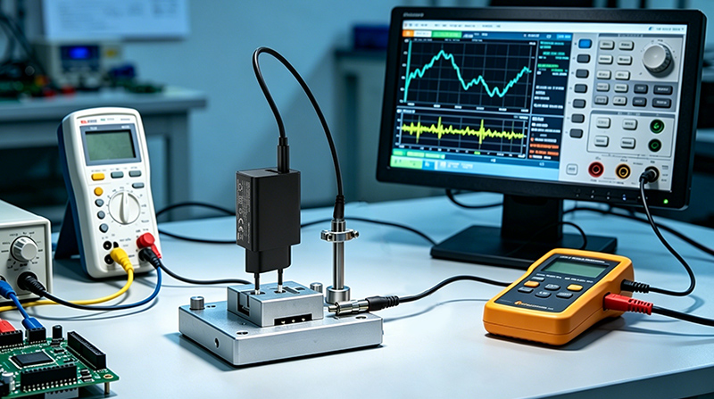
Power adapter specifications affect device performance by determining the stability of power delivery, the level of electromagnetic interference, and the efficiency of energy conversion under load. High-quality power adapter specifications ensure your device functions smoothly without screen flicker, signal noise, or processing lags.
How Does Ripple Voltage Degrade Signal Quality?
Ripple voltage is the small, unwanted AC fluctuation left over after converting AC power to DC. High ripple voltage acts as electrical noise, interfering with delicate data streams and analog signals.
Bottom line:
- Display Flicker: Uncontrolled ripple creates visible interference lines on LCD monitors and touch panels.
- Sensor Inaccuracy: Precise analog measurements get corrupted by high-frequency electrical noise.
- Wireless Interference: Poorly filtered DC lines generate EMI, reducing Wi-Fi and Bluetooth connection ranges.
Specifying low ripple and noise parameters keeps your system’s data lines clean and running at maximum speed.
What Role Does Efficiency Level Play?
An adapter’s efficiency rating determines how much power is converted into usable electricity versus how much is wasted as heat. High-efficiency ratings are essential for meeting green B2B procurement standards.
Think about it:
- Department of Energy (DoE) Level VI: Strictly regulates how much standby energy an idle adapter can consume.
- Cooler Operating Footprint: Highly efficient adapters emit very little heat, keeping surrounding electronics cool.
- Reduced Total Energy Costs: Using energy-efficient adapters across large deployments drastically cuts utility bills.
Choosing highly efficient conversion specifications directly translates to cooler running temperatures and stable system clocks. Key Takeaway: Demanding high efficiency and low noise ratings keeps data lines clean and reduces overall power operating costs.
| Performance Parameter | Standard Spec Limit | Premium Spec Target | Device Impact | |
|---|---|---|---|---|
| Ripple and Noise | < 100 mV Peak-to-Peak | < 50 mV Peak-to-Peak | Smooth analog signals, reliable sensors | |
| Efficiency Standard | Below DoE Level VI | DoE Level VI Compliant | Reduced heat output, lowered power bills | |
| Voltage Regulation | +/- 5.0% Variation | +/- 1.0% Steady State | Stable logic clocks, zero erratic reboots |
Specify ultra-low ripple rates to ensure data signal integrity across industrial networks.
Why Is Connector Type Important in Power Adapter Specifications?
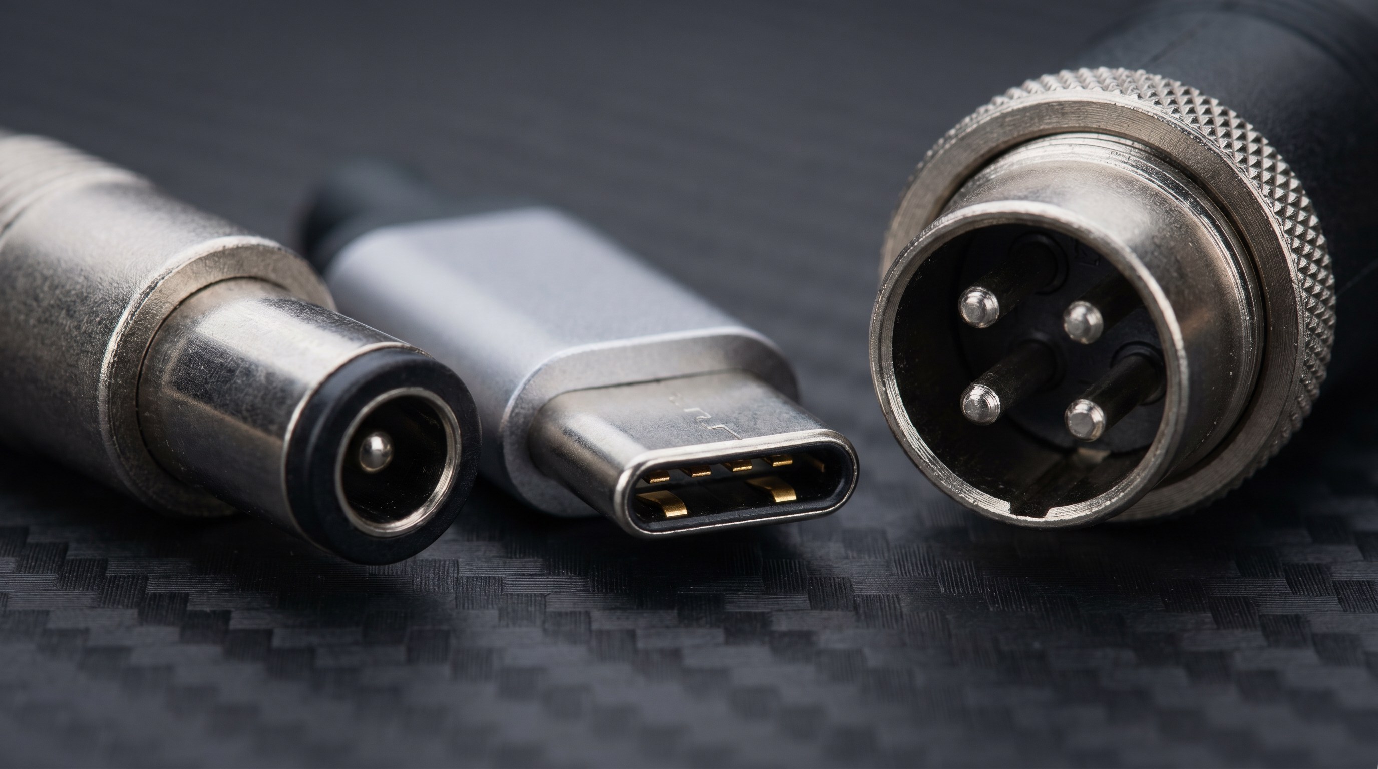
Connector type is critical in power adapter specifications because it ensures secure physical mating and prevents incorrect voltage connections to mismatched hardware interfaces. Matching these physical power adapter specifications prevents loose connections, arcing, and accidental disconnection.
What Are Common Barrel Connector Sizes?
Barrel connectors are the most common plug type for DC power applications, but they come in dozens of highly similar outer and inner diameter combinations. A tiny 0.4mm difference is enough to cause intermittent power drops.
Here is the catch:
- 5.5mm x 2.1mm vs. 5.5mm x 2.5mm: A 2.5mm pin plug will physically fit into a 2.1mm jack, but it will make a loose, unreliable electrical connection.
- Connector Length Variances: Barrel lengths typically range from 9.5mm to 12mm, affecting how deeply the plug sits in the port.
- Spring-Loaded Contacts: High-quality jacks use internal leaf springs to maintain tight electrical contact over thousands of connection cycles.
Confirming exact mechanical drawings prevents intermittent connections and keeps your devices powered reliably.
How Do USB-C and Proprietary Connectors Compare?
Modern high-power devices are rapidly moving away from simple barrel plugs toward USB-C Power Delivery or ruggedized multi-pin locking connectors.
But wait, there’s more:
- USB-C Power Delivery (PD): Uses built-in communication chips to negotiate variable voltages (e.g., 5V, 9V, 15V, 20V) safely.
- Lockable DIN Plugs: Prevent accidental unplugging in high-vibration industrial or medical environments.
- Keyed Polarized Shells: Physically prevent users from plugging an incorrect power source into a sensitive data port.
Selecting a locking or smart physical interface mitigates the risks of field failures due to human error. Key Takeaway: Matching precise connector dimensions and locking structures prevents mechanical wear and eliminates intermittent connection drops.
| Connector Family | Connection Mechanism | Max Power Target | Common Field Application | |
|---|---|---|---|---|
| Standard Barrel | Friction-fit sleeve | Up to 100 Watts | Commercial electronics, small IoT hubs | |
| Locking DIN | Twist-lock or bayonet | Over 150 Watts | Medical displays, heavy industrial gears | |
| USB-C Power Delivery | Spring-locked snap | Up to 240 Watts | Modern laptops, smartphones, tablets |
Align connector mechanics with your physical environment to avoid field disconnected states.
How Do Polarity Requirements Fit Into Power Adapter Specifications?
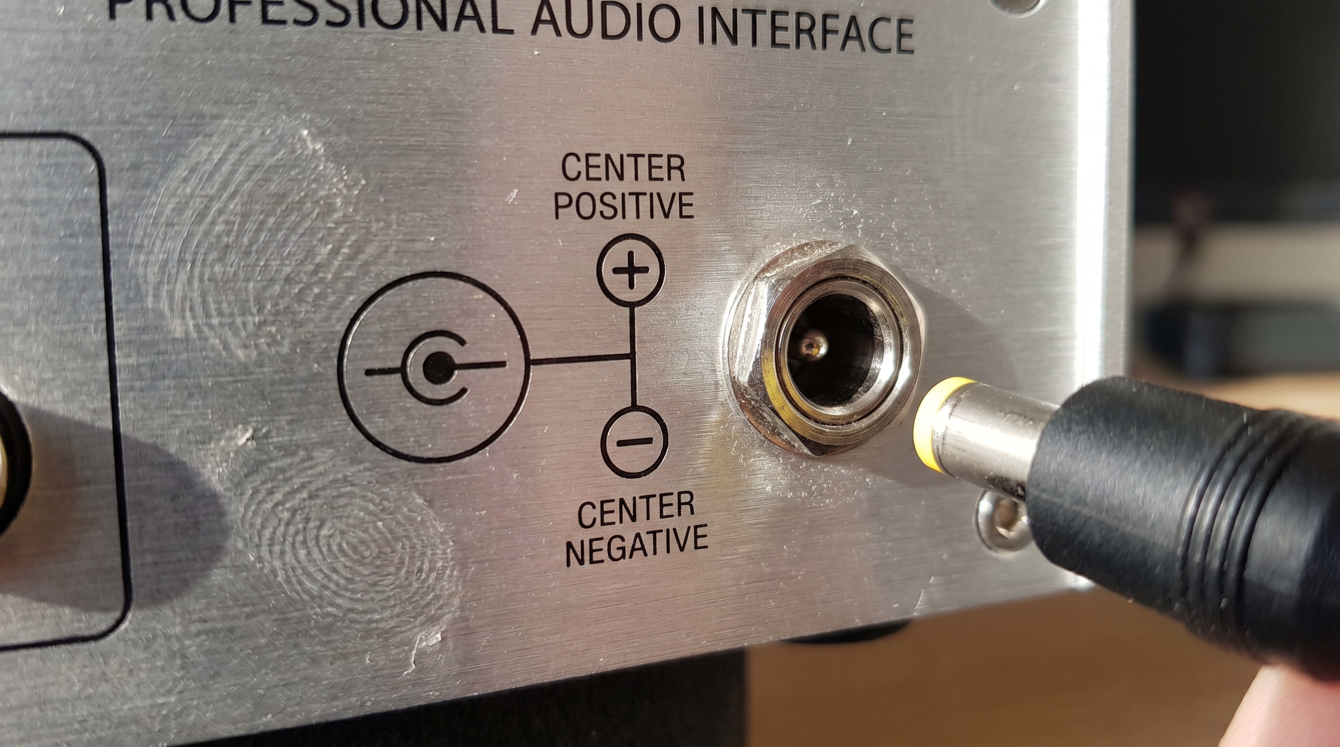
Polarity requirements fit into power adapter specifications by determining the direction of current flow through the positive and negative terminals of the DC connector. Verifying these power adapter specifications is essential because reversing polarity will instantly destroy non-protected electronic components.
What Is Center-Positive vs. Center-Negative?
DC power requires a complete, directional circuit loops with a positive path and a negative path. The polarity icon on an adapter housing indicates which terminal is positive and which is negative.
Look closely:
- Center-Positive (Standard): The inner pin carries the positive voltage (+), while the outer sleeve acts as the ground return (-).
- Center-Negative (Specialized): The outer sleeve carries the positive voltage (+), while the inner pin is the ground return (-).
- Polarity Symbols: Always represented by a diagram showing three circles connected by lines to indicate polarity layout.
Understanding these diagrams is vital, as connecting a center-negative adapter to a center-positive device is an immediate safety hazard.
What Happens During a Reverse Polarity Event?
If you plug an adapter with the wrong polarity into an unprotected device, current will flow backward through sensitive diodes and integrated circuits, frying them instantly.
The reality is:
- Silicon Gate Fusion: Transistors inside chips instantly melt from backward current flow.
- Blown Protection Diodes: If the device has reverse polarity protection, the sacrificial input diode will blow to save the downstream board.
- PCB Copper Delamination: The high current generated by a reverse short can superheat and destroy internal circuit board traces.
Reversing polarity is a zero-tolerance mistake that almost always leads to catastrophic component death. Key Takeaway: Double-checking the schematic polarity icons before power-up keeps your internal boards completely safe from backward currents.
| Polarity Type | Schematic Icon Description | Common Hardware Target | |
|---|---|---|---|
| Center-Positive | Negative sleeve (-) linked to positive pin (+) | Standard consumer, IT, and industrial hardware | |
| Center-Negative | Positive sleeve (+) linked to negative pin (-) | Analog musical instruments, specialized audio gear |
Always match schematic symbols on both device and power supply enclosures before energizing.
Which Certifications Matter in Power Adapter Specifications?
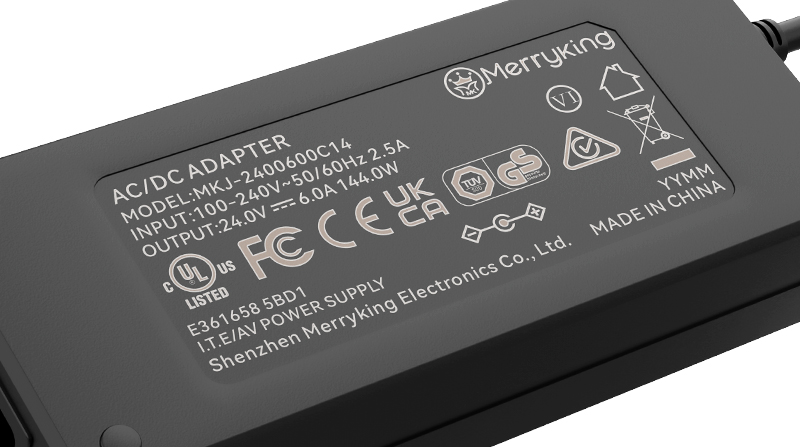
Regulatory certifications matter in power adapter specifications because they guarantee the unit complies with international safety, electromagnetic compatibility, and environmental protection laws. Sourcing units with certified power adapter specifications is mandatory for legal compliance and risk mitigation in B2B markets.
What Are Major Global Safety Marks?
Safety marks prove that an independent, accredited laboratory has thoroughly tested the power adapter under extreme conditions to ensure it will not catch fire or shock the user.
You might wonder:
- UL / cUL Listed: The gold standard safety certification required to legally sell electrical equipment in the US and Canada.
- CE Mark: The self-declaration mark needed for entry into the European Economic Area, proving compliance with safety directives.
- PSE & CCC Marks: Highly specific safety and performance approvals required for the Japanese and Chinese markets, respectively.
Acquiring adapters with these global safety marks protects your business from major product liability lawsuits.
Why Check for EMC and Environmental Compliance?
An adapter must not emit excessive electromagnetic interference that could disrupt nearby communications, and it must not contain hazardous materials that harm the environment.
Why does this matter?
- FCC Part 15 / EN 55032: Limits the amount of electromagnetic noise the adapter can emit back into the power lines or air.
- RoHS Directive: Certifies the product is free from hazardous materials like lead, cadmium, and mercury.
- WEEE Compliance: Ensures the manufacturer has a responsible recycling system in place for end-of-life electronics.
Certified adapters guarantee your final product can legally cross borders and pass custom inspections. Key Takeaway: Specifying fully certified power modules prevents costly custom delays and ensures compliance with strict B2B safety audits.
| Certification Mark | Target Territory | Regulatory Scope | |
|---|---|---|---|
| UL / cUL | North America | Electrical safety, insulation, and shock prevention | |
| FCC / CE | US / Europe | Electromagnetic noise and radio frequency interference limits | |
| RoHS / REACH | Europe / Global | Banning toxic compounds to protect environmental safety |
Verify regulatory validity by searching lab databases to protect your company from compliance audits.
What Spec Mistakes to Avoid in Power Adapter Specifications?

The most common spec mistakes to avoid in power adapter specifications include ignoring polarity signs, undersizing the current rating, neglecting thermal derating factors, and choosing uncertified clones. Sidestepping these mistakes when analyzing power adapter specifications protects your hardware and brand reputation.
How Dangerous Is Buying Non-Certified Clones?
In an effort to cut costs, some procurement teams buy cheap, uncertified alternative power adapters. These generic clones almost always lack critical safety features and fail to match their labeled performance ratings.
Think about it:
- Mislabeled Ratings: Generic units are often labeled as 3-Amp adapters but can only deliver 1.5 Amps before failing.
- Omitted Safety Circuits: Low-cost clones typically skip short-circuit, over-voltage, and over-temperature safety protection.
- Poor Construction Quality: Weak isolation barriers between high-voltage AC and low-voltage DC lines create massive shock hazards.
The tiny upfront savings of buying cheap adapters are quickly wiped out by high field failure rates and product liability claims.
Why Is Ignoring Thermal Derating a Critical Error?
An adapter’s rated power capacity is measured under perfect laboratory temperatures (typically 25°C). In real-world environments, such as inside closed cabinets, power capacity drops sharply as heat rises.
Here is the cold, hard truth:
- Declining Output Power: Most power supplies must be derated by 2% to 5% for every degree above 40°C.
- In-Cabinet Heat Trapping: A power brick operating at full load inside an unventilated housing can easily trigger early thermal shutdowns.
- Component Lifespan Halving: For every 10°C increase in internal operating temperature, capacitor lifespans are cut in half.
A failure to account for real-world environmental factors leads directly to premature field failures. Key Takeaway: Sourcing power components that are rated for actual field temperatures prevents sudden equipment crashes and extends device lifespan.
| Engineering Oversight | Direct Hardware Impact | Correct Alternative Practice | |
|---|---|---|---|
| Selecting Cheap Clones | Severe shock risk and high failure rates | Procure exclusively from audited, certified manufacturers | |
| Ignoring Thermal Limits | Constant thermal shutdowns under loads | Specify industrial units with extended temperature margins | |
| Relying on “Universal” Kits | Poor mechanical fit and incorrect voltage | Design-in a single, dedicated power supply for safety |
Ensure your procurement specifications reflect real-world operating environments rather than theoretical minimums.
How to Customize Power Adapter Specifications for Your Device?
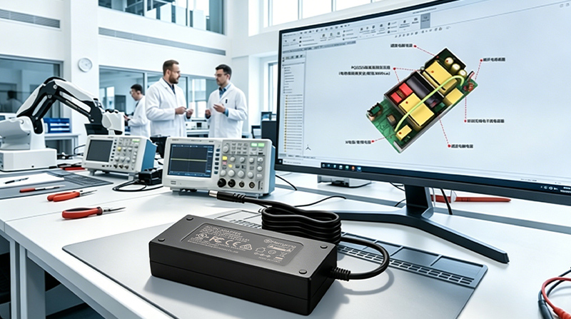
Customizing power adapter specifications for your device involves collaborating with a professional manufacturer to tailor output parameters, connector types, cable lengths, and custom enclosure branding. Developing bespoke power adapter specifications ensures a perfect match for specialized industrial, medical, or consumer applications.
When Should You Opt for Custom Designs?
Standard off-the-shelf adapters work well for standard designs, but specialized B2B hardware often requires customized power specifications to meet unique operating demands.
The choice is clear:
- Non-Standard Voltage Rails: High-performance devices sometimes require unique voltage rails like 17.5V or 36V.
- Extreme Operating Environments: Outdoor or marine installations require custom weatherproofing and IP67 waterproof ratings.
- Strict Safety Standards: Medical systems require double-insulated enclosures and ultra-low leakage current ratings (MOPP standards).
Custom power supplies ensure you never have to compromise your primary product design to fit a standard power block.
What Details Must You Provide to Manufacturers?
To engineer a custom power solution, you must supply your manufacturing partner with a complete list of your device’s electrical, environmental, and physical constraints.
Here is your roadmap:
- Peak Power Profiles: Share detailed charts showing your device’s startup power surges and steady running states.
- Mechanical Footprints: Provide CAD models showing how the adapter must mount or integrate into your system enclosure.
- Expected Compliance Standards: Specify which international safety and environmental certifications your final system must pass.
Custom engineering eliminates operational compromises and guarantees seamless brand integration. Key Takeaway: Partnering with a dedicated OEM power adapter manufacturer enables you to optimize device form factor and ensure complete compliance.
| Custom Development Phase | Primary Engineer Action | Desired Deliverable Outcome | |
|---|---|---|---|
| Requirement Phase | Share electrical profile, CAD files, and certifications | Precise product specification blueprint | |
| Prototyping Phase | Conduct laboratory testing under real environmental stress | Validated safe operating limits and performance data | |
| Mass Production Phase | Establish quality assurance parameters for manufacturing | Consistent delivery of optimized power solutions |
Integrate customized power supply parameters early in your design phase to expedite your market launch.
Technical Summary
By methodically matching output voltage, current capacities, physical connectors, and global safety standards, you eliminate electrical risks and guarantee stable long-term performance. Our engineering team at MK Power Adapter stands ready to help you analyze peak power profiles and customize robust, certified power modules. We envision a future of highly efficient, safe, and green energy conversion powering global hardware innovation. To partner with our technical experts and accelerate your product development, contact us today .
Frequently Asked Questions
Can I use a power adapter with higher voltage than my device requires?
No. Utilizing high voltage will immediately overload sensitive silicon gates, melt internal paths, and cause irreversible board failures. You must always match the voltage specification exactly to prevent destroying your hardware.
What’s the best way to verify center-positive polarity on a device?
Check the device’s input label for the visual polarity symbol showing a plus (+) sign connected to the center circle. If the label is faded, refer to the manufacturer’s technical datasheets or circuit schematic diagrams to verify contact paths.
Can I use an adapter with higher amperage than my device asks for?
Yes. The device dynamically draws only the exact current it needs, leaving the extra capacity as safe thermal headroom. Operating with oversized amperage capacity prevents the power adapter from running at its absolute limit, keeping it cool and extending its lifetime.
How do I know if my power adapter needs medical-grade certifications?
Determine if your final system is going to be used in near-patient hospital environments. If so, standard commercial power supplies are illegal, and you must select modules certified to IEC 60601-1 standards to ensure ultra-low electrical leakage levels.
What’s the best way to prevent accidental adapter disconnections in industrial settings?
Specify threaded barrel ports, lockable DIN connectors, or snap-fit USB-C interfaces that resist physical vibrations and cable pulling. Integrating lockable mechanical housings ensures high contact pressure and continuous operational uptime on the assembly line.