EMI and EMC components in power adapters are specialized electronic parts designed to suppress electromagnetic interference and ensure compliance with global electromagnetic compatibility standards. Imagine your engineering team gathered around the test bench, watching the analyzer screen as your new product fails its final compliance run due to unexpected line noise spikes. The sting of rejection hits hard as you realize this single failure translates directly into months of delayed product launches, wasted engineering hours, and mounting laboratory re-testing fees. Fortunately, selecting the right high-performance EMI EMC components in power adapters provides the ultimate safety net, allowing you to easily suppress unwanted noise at the source and clear regulatory hurdles with confidence.
① What Are EMI EMC Components in Power Adapters?
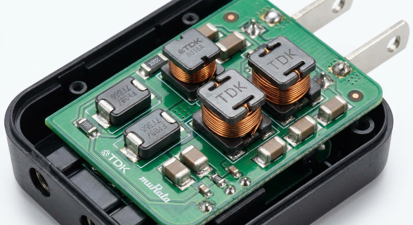
EMI EMC components in power adapters are specialized electronic parts like inductors, capacitors, and beads designed to manage and attenuate electromagnetic interference generated during high-frequency electrical switching. When you integrate high-reliability EMI EMC components in power adapters , they serve as the primary defensive shield against disruptive high-frequency electrical noise. These dedicated elements actively prevent power supplies from sending unwanted electrical noise back into the grid or radiating it through the air.
In switched-mode power supplies, the rapid switching of internal transistors naturally creates parasitic voltages that require immediate mitigation. Without these passive and active suppressors, sensitive downstream electronics would fail to operate correctly due to severe signal degradation.
Can You Differentiate Conducted Noise from Radiated Noise?
Why does this matter? Conducted noise travels along the physical power cords and wires directly into other connected devices, while radiated noise travels through the air as electromagnetic waves. If you want your products to pass global compliance tests, you must understand how both types of noise bypass your primary circuits.
Here is the deal:
- Conducted emissions are typically managed using input filters, common mode chokes, and safety capacitors.
- Radiated emissions are suppressed using metal shielding, optimized PCB layouts, and strategically placed ferrite beads.
Ignoring these separate propagation paths will lead to unexpected diagnostic confusion during laboratory sweeps. By designing a balanced filtering strategy, you protect your power supply from being both an emitter of electrical noise and a victim of external surges.
Key Takeaway: Implementing a clear separation between conducted and radiated mitigation strategies ensures your adapter remains compliant with international grid laws while preserving signal integrity.
| Component Type | Primary EMI/EMC Role | Typical Circuit Location | |
|---|---|---|---|
| Common Mode Choke | Suppresses conducted common-mode noise | AC Line Inlet Stage | |
| Safety Y-Capacitors | Diverts common-mode noise to ground | Primary-to-Secondary Isolation Barrier | |
| Safety X-Capacitors | Attenuates differential-mode noise | Across AC Line and Neutral |
This comparison highlights how different components target distinct noise paths within your power adapter’s physical layout.
② Why Are EMI EMC Components in Power Adapters Important?

EMI EMC components in power adapters are critically important because they guarantee that the electrical power supply operates safely without corrupting the local power grid or causing neighboring devices to malfunction. Choosing high-quality EMI EMC components in power adapters is a mandatory safety and legal requirement for commercial distribution worldwide. If you leave high-frequency electrical noise completely unchecked, it will inevitably disrupt wireless communications and cause unexpected system failures.
These parts also shield your adapter’s internal circuitry from external power grid spikes like lightning strikes or static discharges. By preserving clean power delivery, you ensure the long-term durability of the entire electronic system.
How Do They Accelerate Your Global Market Access?
Think about it: failing an expensive EMC compliance test can set your product launch timeline back by several months. When you design with top-tier components from the start, you protect your budget from costly redesign loops and redundant lab fees.
To achieve quick approval, you must meet several key international standards:
- FCC Part 15 Class B for residential and commercial usage in North America.
- CISPR 32 / EN 55032 for marketing electronics throughout the European Union.
- IEC 60601-1-2 for demanding medical-grade equipment environments.
Best of all, having these built-in compliance elements means your product is instantly ready for a friction-free international launch.
Key Takeaway: Prioritizing compliance components during the initial design phase eliminates unexpected regulatory barriers and gets your product to market ahead of your competition.
| Target Standard | Geographic Scope | Legal Implications | |
|---|---|---|---|
| FCC Part 15 Class B | United States / North America | Mandatory for commercial & consumer import | |
| CISPR 32 / EN 55032 | European Union / Global | Required for CE marking and market access | |
| IEC 60601-1-2 | Global Medical Markets | Crucial for safety-critical clinical environments |
Meeting these strict regulatory frameworks from the outset protects your business from custom seizures and costly legal disputes.
③ How Do EMI EMC Components in Power Adapters Reduce Interference?
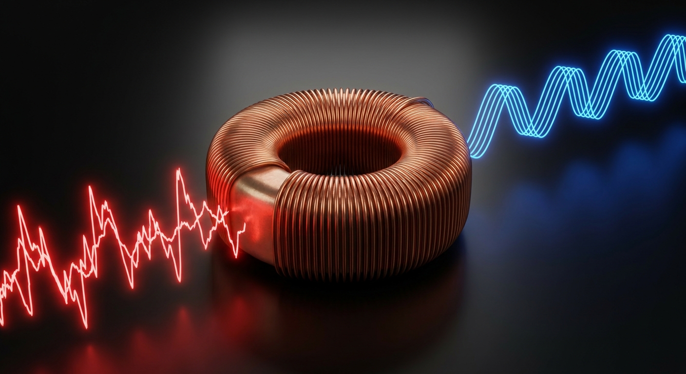
EMI EMC components in power adapters reduce interference by creating high-impedance barriers that block high-frequency electrical noise while providing low-impedance paths to safely divert unwanted currents. Utilizing proper EMI EMC components in power adapters allows you to effectively filter conducted noise and shield radiated magnetic fields. By altering the impedance characteristics of the circuit paths, these parts convert destructive electrical energy into harmless thermal dissipation.
This continuous filtering process stabilizes the voltage lines and keeps power delivery exceptionally smooth. It is the primary engineering mechanism used to preserve clear signals in modern electronics.
Can You Shield Radiated Fields from Switching Nodes?
Here is the deal: high-frequency switching nodes inside power supplies act like miniature radio antennas if they are not properly shielded. When you utilize Faraday cages or conductive metal enclosures, you block these dangerous electromagnetic waves from escaping.
To block noise effectively, your design must deploy multiple defense mechanisms:
- Inductive filtering to block high frequencies using series inductors.
- Capacitive shunting to redirect common-mode currents back to the source.
- Physical shielding to absorb or reflect radiated airborne fields.
Why does this matter? Combining these techniques ensures your electronic systems remain quiet and highly stable.
Key Takeaway: Combining active physical shielding with passive inductive filtering creates an impenetrable defense against both airborne and cable-bound noise.
| Mitigation Method | Component Mechanism | Targeted Frequency Range | |
|---|---|---|---|
| Inductive Filtering | High impedance via magnetic flux storage | 150 kHz – 30 MHz (Conducted) | |
| Capacitive Shunting | Low impedance path to return/ground | 150 kHz – 30 MHz (Conducted) | |
| Enclosure Shielding | Reflection and absorption of EM waves | 30 MHz – 1 GHz (Radiated) |
Integrating multiple mitigation levels ensures that your power adapters meet both conducted and radiated emission limits seamlessly.
④ Which EMI EMC Components in Power Adapters Are Commonly Used?
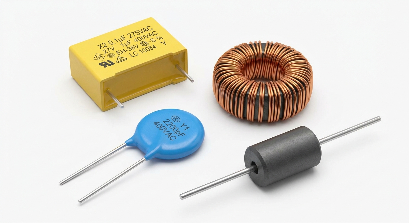
The most commonly used EMI EMC components in power adapters include common mode chokes, Class X and Class Y safety capacitors, and ferrite beads. Each of these EMI EMC components in power adapters targets a specific frequency range and electrical noise path to ensure comprehensive circuit protection. Selecting the ideal mix of these parts allows you to construct a robust, highly efficient input filter stage.
These components must be rated correctly to withstand continuous thermal loads and sudden power surges from the mains grid. Choosing the wrong parts can compromise both the safety and performance of your product.
Why Do Safety Ratings Matter for Passive Elements?
Think about it: a failure in a standard capacitor could lead to a catastrophic electrical fire or give your end-user a severe electric shock. That is why safety agencies mandate the use of specially certified X and Y capacitors across critical nodes.
When choosing these components, you must verify several key parameters:
- Class X capacitors must be selected for line-to-neutral connections.
- Class Y capacitors are required for line-to-ground isolation paths.
- Common mode chokes must handle the maximum continuous input current without saturating.
Best of all, using certified components gives you instant credibility with international safety auditors.
Key Takeaway: Standardizing on certified safety components safeguards your end-users from shock hazards while establishing a solid foundation for overall regulatory compliance.
| Key Component | Key Electrical Parameter | Safety / Rating Class | |
|---|---|---|---|
| X-Capacitor | Capacitance, Rated AC Voltage | X1 (Surge up to 4kV), X2 (Surge up to 2.5kV) | |
| Y-Capacitor | Isolation Voltage, Leakage Current | Y1 (Double Isolation), Y2 (Basic Isolation) | |
| Common Mode Choke | Inductance, Rated Current, DCR | Custom designed based on switching frequency |
This parameter comparison shows why selecting safety-rated parts is a critical step in high-voltage power supply engineering.
⑤ How Do Common Mode Chokes Work as EMI EMC Components in Power Adapters?
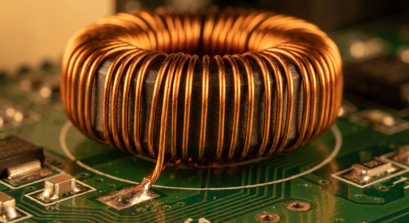
Common mode chokes work as EMI EMC components in power adapters by presenting a highly resistive impedance to unwanted common-mode noise while allowing desirable differential-mode currents to pass unimpeded. Installing these highly effective EMI EMC components in power adapters is crucial for canceling out identical noise signals that travel on both the line and neutral wires. They utilize a dual-winding design around a single magnetic core to achieve this selective noise cancellation.
Because the magnetic fluxes generated by the opposing power currents cancel each other out, the core does not saturate under heavy normal loads. This physics-based mechanism makes common mode chokes highly reliable for high-power applications.
Can You Prevent Core Saturation Under Heavy Currents?
Here is the deal: if your magnetic core saturates, its inductance drops to zero, rendering your common mode choke completely useless. You must select core materials with high saturation flux densities to ensure consistent filtering performance even under heavy loads.
To optimize your choke selection, keep these rules in mind:
- Manganese-Zinc cores should be selected for low-frequency noise.
- Nickel-Zinc cores are ideal when you need to target higher-frequency interference.
- DC resistance (DCR) must be kept as low as possible to prevent excess heat.
Why does this matter? Sizing the choke correctly ensures your filter performs flawlessly under real-world operating conditions.
Key Takeaway: Matching the core material to your target noise frequency spectrum prevents premature saturation and preserves continuous common-mode attenuation.
| Core Material | Target Frequency | Key Advantage | |
|---|---|---|---|
| Mn-Zn (Manganese-Zinc) | 150 kHz – 5 MHz | High permeability, great low-frequency performance | |
| Ni-Zn (Nickel-Zinc) | 5 MHz – 30 MHz | High resistivity, excellent high-frequency attenuation | |
| Amorphous Core | Broad Spectrum | Exceptional thermal stability and compact size |
Choosing the right magnetic core chemistry is vital to maintaining filtering effectiveness across your power supply’s full thermal envelope.
⑥ Why Are X Capacitors and Y Capacitors Important EMI EMC Components in Power Adapters?
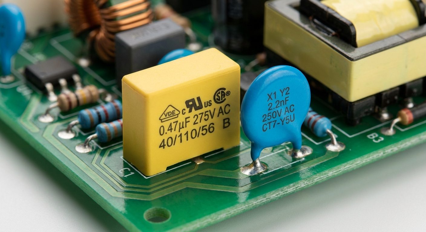
X and Y capacitors are important EMI EMC components in power adapters because they provide essential high-frequency bypass paths that safely shunt noise currents away from sensitive active circuits. These safety-certified EMI EMC components in power adapters prevent dangerous high-voltage spikes from damaging downstream components or shocking end-users. Their specific mechanical designs ensure that they fail safely under extreme overvoltage conditions.
Class X capacitors handle differential-mode noise by bridging the AC lines directly, while Class Y capacitors manage common-mode noise by connecting the lines directly to ground. These parts are fundamental to structural safety design.
Do You Know How Safety Failure Modes Protect Users?
Why does this matter? If an X capacitor fails, it is designed to short-circuit, immediately tripping the safety fuse and cutting off power before a fire can start. On the other hand, if a Y capacitor fails, it is designed to open-circuit, preventing any hazardous mains voltage from reaching the chassis where you might touch it.
You must carefully evaluate these parameters during safety audits:
- Total leakage current through the Y capacitors must remain within legal safety bounds.
- Surge tolerance ratings must match your geographic distribution markets.
- Dielectric materials must withstand continuous high thermal stress without degrading.
Best of all, using certified safety capacitors ensures your power adapters remain completely safe throughout their operational lifespans.
Key Takeaway: Understanding safety-rated capacitor failure behaviors allows you to design power supplies that actively prevent fires and shock hazards during field failures.
| Capacitor Class | Placement Node | Failure Behavior | Safety Function | |
|---|---|---|---|---|
| Class X | Line to Neutral | Fails Short | Trips fuse to prevent fire | |
| Class Y | Line to Ground | Fails Open | Prevents electrical shock to user |
These safety-critical failure mechanisms are non-negotiable requirements for obtaining global consumer safety approvals.
⑦ How Do Ferrite Beads Function as EMI EMC Components in Power Adapters?
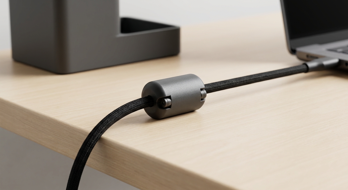
Ferrite beads function as EMI EMC components in power adapters by acting as high-frequency resistors that suppress parasitic oscillations and dissipate electrical noise as harmless heat. Integrating these high-frequency EMI EMC components in power adapters provides a highly focused tool for eliminating high-frequency ringing on switching nodes and cables. They are highly effective at suppressing noise above 30 MHz, where traditional inductors lose their efficiency.
By placing them directly on component leads or cables, you prevent high-frequency transients from radiating into the environment. This makes ferrite beads a vital addition to any low-noise power adapter design.
Can Ferrite Beads Solve Your Radiated Cable Noise?
Think about it: power cords often act as antennas, broadcasting high-frequency noise directly into the surrounding airspace. When you snap a ferrite bead onto your DC output cable, you instantly block this radiated noise from escaping.
To maximize the efficiency of ferrite beads, follow these design practices:
- Position them as close to the noise-generating switching node as possible.
- Match the bead’s impedance peak to your target noise frequency.
- Verify that the continuous DC current does not cause magnetic saturation.
Best of all, ferrite beads offer an incredibly cost-effective way to fix eleventh-hour radiated emissions issues without requiring a complete board redesign.
Key Takeaway: Using ferrite beads on output lines provides a powerful, low-cost solution for suppressing high-frequency cable emissions without changing your PCB layout.
| Frequency Range | Suppression Mechanism | Target Application | |
|---|---|---|---|
| Low Frequency (<10 MHz) | Inductive reactance | Power supply line filtering | |
| High Frequency (30-500 MHz) | Resistive dissipation | Cable ringing and radiated suppression | |
| Ultra-High Frequency (>500 MHz) | High impedance blocking | Precision RF shielding applications |
Sizing and placing ferrite beads strategically allows you to target precise high-frequency bands with surgical accuracy.
⑧ How Are EMI EMC Components in Power Adapters Tested for Compliance?
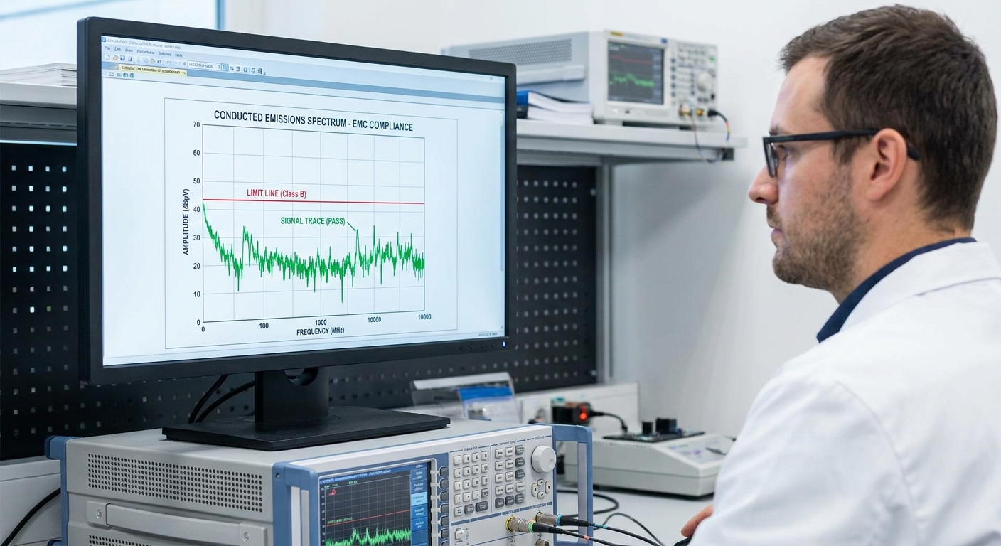
EMI EMC components in power adapters are tested for compliance using specialized laboratory receivers, anechoic chambers, and Line Impedance Stabilization Networks (LISNs) to measure exact noise emissions. Verifying the performance of your EMI EMC components in power adapters through certified testing laboratories is the only legal path to commercial distribution. These testing protocols evaluate both how much noise your power supply emits and how well it resists external power surges.
Passing these evaluations confirms that your product will not cause local power grid failures or fail during electrostatic discharge events. It represents the ultimate proof of quality for your power supply system.
Do You Need In-House Pre-Compliance Testing?
Here is the deal: booking time at a certified compliance laboratory can cost thousands of dollars per day, and a single failure means you have to pay the full amount all over again. By setting up basic pre-compliance testing tools in your own workshop, you can catch and fix major noise spikes early.
Your testing process should cover these essential components:
- Conducted emissions testing using a LISN and a spectrum analyzer.
- Radiated emissions testing in a shielded or semi-anechoic environment.
- Surge immunity testing to confirm survival against mains voltage spikes.
Why does this matter? Catching emissions issues during the prototyping stage guarantees a smooth, first-time pass during your final lab audits.
Key Takeaway: Conducting in-house pre-compliance testing drastically reduces certification costs and protects your product development timeline from unexpected delays.
| Test Category | Equipment Required | Compliance Objective | |
|---|---|---|---|
| Conducted Emissions | LISN, Spectrum Analyzer | Measure noise sent back to the power grid | |
| Radiated Emissions | Anechoic Chamber, Antennas | Measure airborne electromagnetic fields | |
| Surge Immunity | Transient Generator | Verify survivability against high-voltage surges |
This standard testing framework shows how compliance labs analyze your power adapter’s noise output before granting global certifications.
⑨ What Problems Occur When EMI EMC Components in Power Adapters Are Poorly Designed?
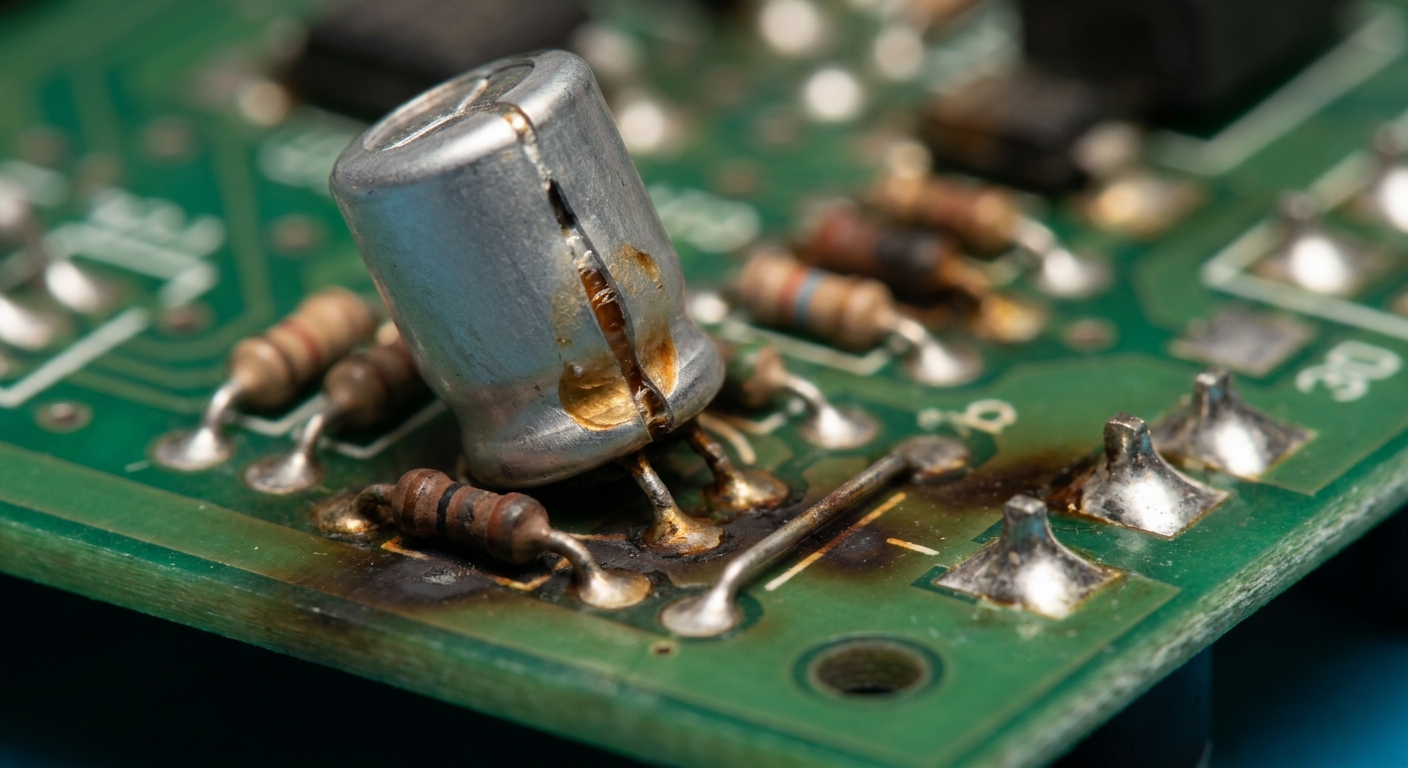
When EMI EMC components in power adapters are poorly designed, they cause severe issues including compliance test failures, massive signal interference, excessive heat generation, and premature component degradation. Utilizing substandard EMI EMC components in power adapters often results in parasitic coupling where high-frequency noise bypasses filter stages entirely. Poor component selection can quickly turn a promising design into a reliability nightmare.
This bad layout can lead to field failures, expensive product recalls, and severe damage to your brand’s market reputation. It is a critical risk factor that requires proactive engineering attention.
Can Parasitic Coupling Ruin Your Best PCB Layout?
Think about it: even if you buy the most expensive common mode choke on the market, a poor PCB layout will let noise couple across copper traces and bypass the filter. You must maintain strict physical separation between noisy switching circuits and quiet input filter lines.
If you do not design with care, you will likely face these severe issues:
- Cross-talk between input and output lines, causing system instability.
- Core saturation under maximum load, resulting in sudden compliance failures.
- Overheated capacitors that dry out and fail years before their rated lifespan.
Best of all, following standard routing guidelines from day one prevents these parasitic coupling problems from ever occurring.
Key Takeaway: Combining high-quality components with an optimized, physically isolated PCB layout is the only way to prevent parasitic noise from ruining your design.
| Design Flaw | Direct Consequence | Long-Term Impact | |
|---|---|---|---|
| Filter Bypass | High-frequency noise leaks directly to the AC cord | Immediate compliance laboratory failure | |
| Core Saturation | Sharp loss of inductance under heavy currents | Massive increase in conducted noise under load | |
| Poor Clearance | Electrical arcing across trace lines | Safety risk, fire hazard, and product recall |
These severe consequences emphasize the absolute necessity of integrating high-quality filter placement rules into your design workflow.
⑩ How Can Manufacturers Optimize EMI EMC Components in Power Adapters?
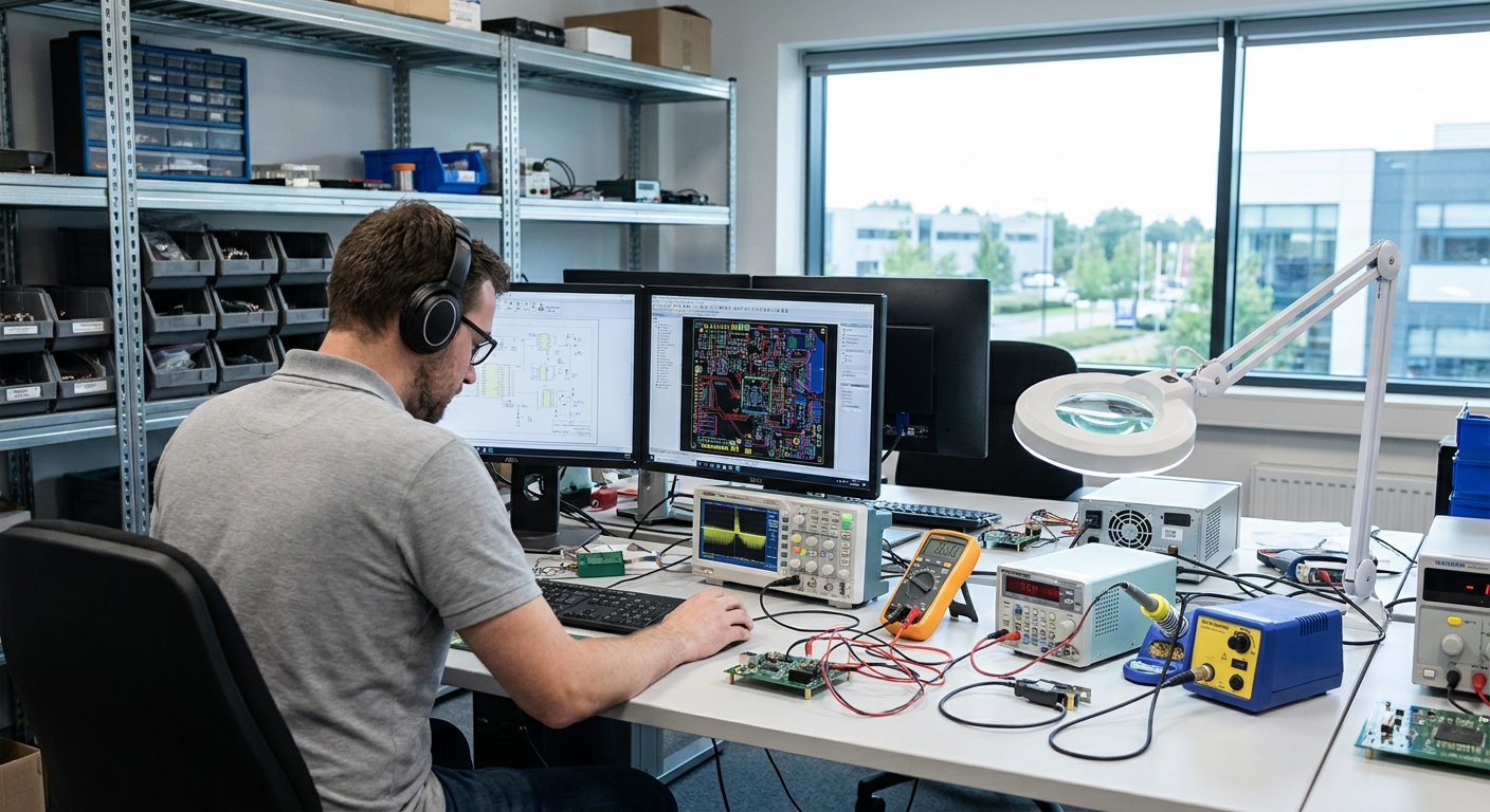
Manufacturers can optimize EMI EMC components in power adapters by using custom-engineered magnetic cores, advanced simulation tools, and strict PCB design rules to reduce overall size while maximizing filtering efficiency. Selecting optimized EMI EMC components in power adapters helps you balance regulatory compliance with cost-effective mass production. By co-designing the filters with the power stage, you achieve superior electrical stability in a much smaller footprint.
This proactive approach minimizes component counts and lowers overall bill-of-materials costs. It represents the gold standard for high-volume consumer and industrial electronics.
Can Simulation Tools Predict Your Compliance Success?
Why does this matter? Utilizing advanced electromagnetic simulation tools allows you to identify hot loops and trace parasitic elements before you ever spin a physical board. This modern design workflow lets you optimize your filter network without wasting weeks on manual trial-and-error tests.
To achieve ultimate optimization, you should focus on these engineering practices:
- Co-designing custom chokes specifically tailored to your adapter’s switching frequency.
- Using simulation software to map out current loops and prevent trace coupling.
- Establishing strong partnerships with vertically integrated component suppliers.
Best of all, optimization yields a lighter, cooler, and highly reliable adapter that easily passes every major global safety test.
Key Takeaway: Standardizing on custom-engineered magnetic components and simulation software allows you to minimize filter size while securing consistent compliance performance.
| Optimization Step | Sourcing Indicator | Manufacturing Advantage | |
|---|---|---|---|
| Custom Magnetics | High-permeability custom cores | 30% reduction in input filter physical space | |
| CAD Simulation | Pre-layout loop analysis | Avoids costly physical PCB revision cycles | |
| Traceability Auditing | 100% component batch tracking | Guarantees consistent quality across mass shipments |
Implementing these optimization steps ensures your power adapters remain highly competitive, cost-effective, and safe.
Conclusion & Action Plan
Integrating high-performance EMI and EMC components into power adapters is essential for ensuring global compliance, long-term product reliability, and clean power delivery. By choosing pre-certified, custom-engineered adapters, you protect your end-system from unexpected design loops and costly certification delays.
If you are developing a new electronic product or looking to optimize an existing design, contact us today to collaborate with our engineering team on a fully compliant, high-reliability power solution tailored to your project requirements.
Frequently Asked Questions
Can I run a power adapter safely without any EMI EMC components?
No, operating a switching power adapter without these components is unsafe and illegal in almost all global markets. Unmitigated electromagnetic noise will cause severe interference with surrounding electronics, and the adapter will fail to pass mandatory safety and emission standards.
What is the best component for blocking common-mode noise?
Absolutely, the common-mode choke is the most effective component for this purpose. Its dual-winding design on a single magnetic core creates high impedance for common-mode noise while allowing differential-mode currents to pass with minimal attenuation.
Can I use standard capacitors instead of safety-rated X and Y capacitors?
No, you must never use standard capacitors for mains filtering applications. Safety-rated X and Y capacitors are specially designed to fail in safe modes (either short-circuiting to trip a fuse or open-circuiting to prevent shock), whereas standard capacitors can fail catastrophically and cause fires or user injuries.
How do I know if my power adapter needs a ferrite bead on its cable?
Typically, you will discover this need during radiated emissions testing if high-frequency noise is escaping via the power cord. If your AC or DC cables act as antennas and push emissions over the legal limit, adding a ferrite bead is the easiest way to suppress these signals.
What’s the best way to prevent magnetic core saturation in my filter chokes?
The most reliable method is to select cores with high saturation flux densities and verify the maximum operating currents. Sizing the magnetic core with a generous margin ensures that high load currents do not reduce the inductor’s filtering effectiveness.