SMD capacitors in power adapters are highly efficient, surface-mounted electronic components designed to optimize space, reduce noise, and ensure stable voltage regulation in modern charging devices. When engineering teams rely on legacy, through-hole components, they inevitably encounter severe spatial limitations, thermal bottlenecks, and compromised efficiency ratings. By transitioning to optimized SMD capacitor in power adapter architectures, you can drastically reduce PCB footprints while ensuring long-term hardware reliability. This technical overview explores how these miniature components revolutionize charging design and power stability.
What Is an SMD Capacitor in Power Adapter Design?
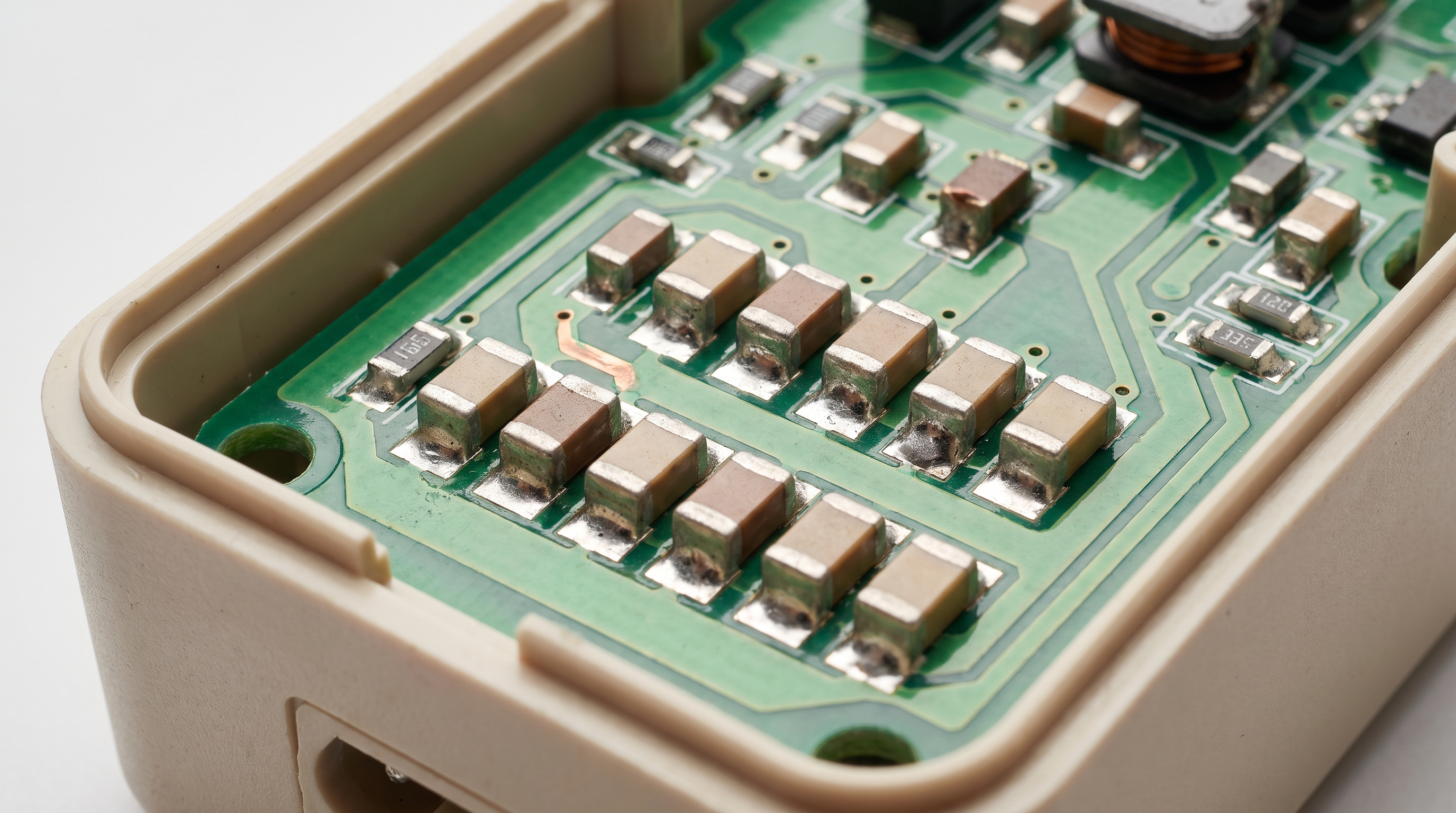
An SMD capacitor acts as a miniature charge-storage reservoir that is soldered directly onto the surface of a power adapter’s printed circuit board. Implementing an SMD capacitor in power adapter topologies allows design teams to eliminate lead-wire parasitics and optimize high-frequency decoupling. This layout choice is crucial for maintaining clean DC outputs.
How Do Surface Mount Devices Differ?
When you transition away from traditional through-hole layouts, you immediately notice how surface mount devices eliminate physical wire leads entirely. Here is the critical distinction:
- No Lead Wires: Eliminates physical pins to reduce equivalent series inductance (ESL).
- Direct Solder Pads: Maximizes mechanical stability and thermal transfer directly to the ground plane.
- Minimal Footprints: Saves up to 70% of PCB real estate compared to standard axial components.
Why Does Size Matter in Modern Adapters?
To meet the modern demand for ultra-compact charging bricks, you must squeeze maximum performance from minimal board space.
- Higher Density: Allows more active components on a single multi-layer board.
- Lower Weight: Reduces overall product mass for enhanced travel portability.
- Shorter Traces: Minimizes trace-induced parasitics that degrade high-frequency signals.
Key Takeaway: Reducing component dimensions increases power density but demands precise thermal dissipation strategies.
| Footprint Code | Dimensions (mm) | Recommended Voltage Range | Primary Application Space | |
|---|---|---|---|---|
| 0402 | 1.0 x 0.5 | 4V – 16V | Ultra-low power signal filtering | |
| 0603 | 1.6 x 0.8 | 6.3V – 50V | High-frequency noise decoupling | |
| 1206 | 3.2 x 1.6 | 10V – 100V | Primary input and output filtration |
Examining how miniature form factors impact thermal dissipation profiles yields crucial design insights.
Why Is an SMD Capacitor in Power Adapter Circuits Important?
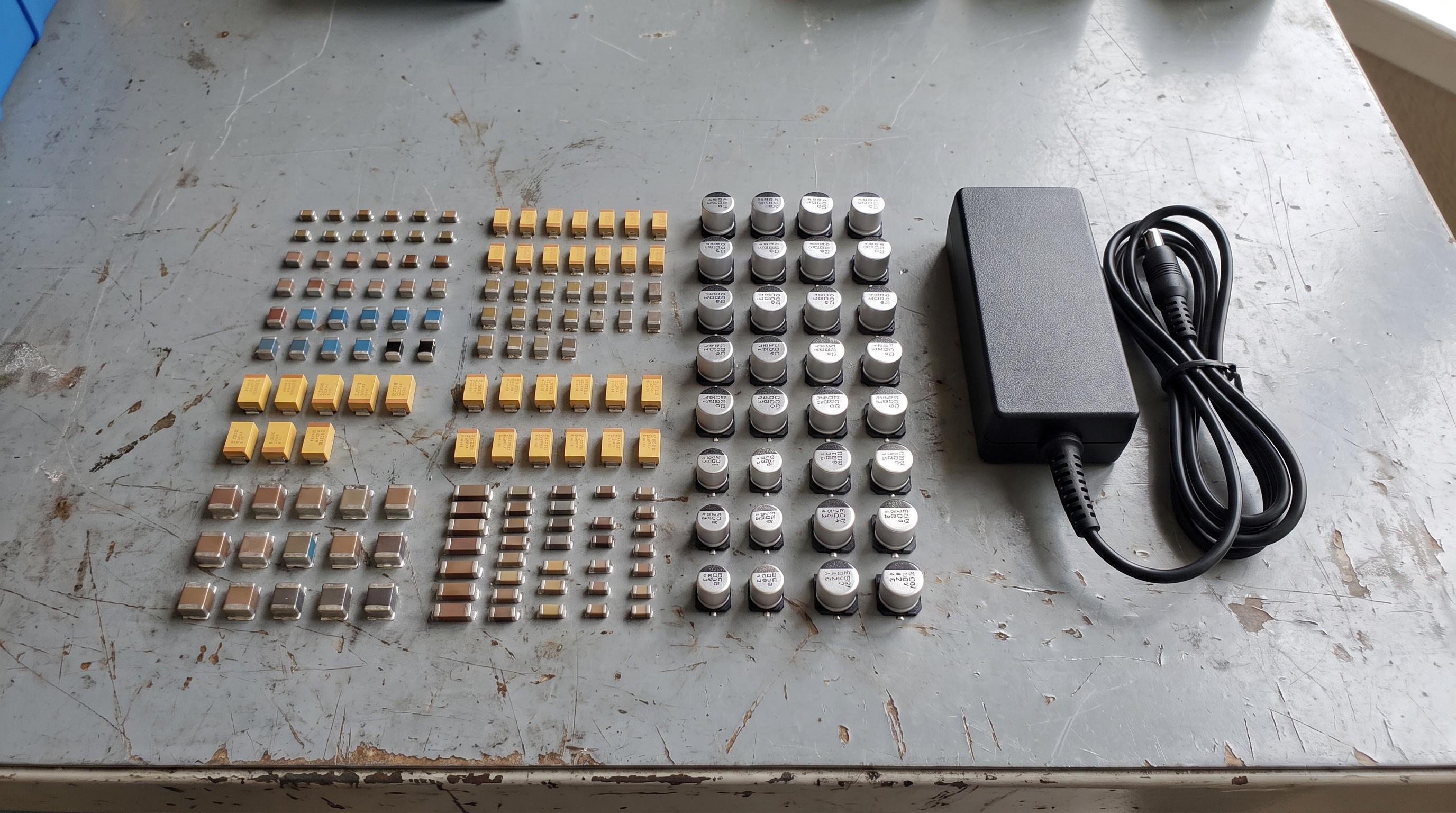
SMD capacitors outperform through-hole components by drastically reducing parasitic inductance and enabling automated, high-speed assembly. Selecting an SMD capacitor in power adapter production bypasses the manual labor bottlenecks and high failure rates associated with wave-soldering leaded components. This transition enhances the overall robustness of your power supply.
What Makes Through-Hole Tech Outdated?
If you are still incorporating radial or axial capacitors, you are introducing unwanted parasitic loops into your circuits. Think about it:
- High Parasitics: Long wire leads act as antennas for unwanted electromagnetic interference (EMI).
- Manual Solder Bottlenecks: Hand-soldering increases human error risks and raises manufacturing overhead.
- Drilled Holes Required: Plated through-holes restrict routing options on multi-layer PCBs.
Are Surface Mount Capacitors More Durable?
When you analyze mechanical durability, you will find that surface mount parts exhibit remarkable resilience against high-vibration stresses.
- Lower Mass: Mitigates inertial forces during drop tests.
- Direct Adhesion: Rigidly bonds to the copper pads to eliminate fatigue on lead wires.
- Co-planar Surface: Distributes mechanical load evenly across the entire board surface.
Key Takeaway: Smaller component masses experience lower mechanical inertia, making them highly resilient against drop-test failures.
| Component Class | Vibration Resistance | Shock Durability | Thermal Expansion Delta | |
|---|---|---|---|---|
| Through-Hole | Poor (leads bend/snap) | Moderate | High (leads absorb stress) | |
| SMD (MLCC) | Excellent (low mass) | High (direct adhesion) | Moderate (requires layout care) |
A mechanical stress evaluation reveals how SMD footprints mitigate structural damage from high-vibration operational environments.
How Does an SMD Capacitor in Power Adapter Filtering Work?
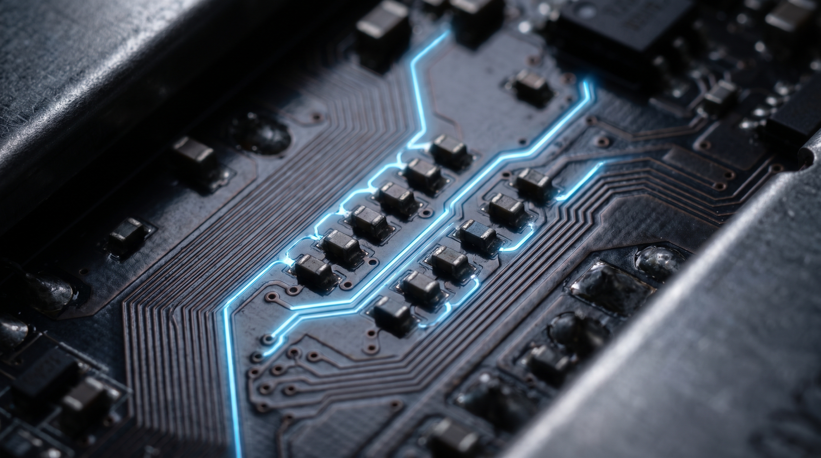
SMD capacitors maximize power adapter efficiency by minimizing energy losses caused by equivalent series resistance (ESR). Integrating an SMD capacitor in power adapter designs helps suppress voltage ripples that otherwise convert clean electrical energy into wasted thermal heat. Merryking’s engineering team prioritizes this design approach to ensure peak system efficiency.
How Do SMD Parts Reduce Power Loss?
When you utilize low-ESR ceramic components, you significantly reduce the internally dissipated energy during rapid switching cycles. What does this mean for you?
- Ultra-low ESR: Decreases internal resistance to mitigate I2R power dissipation.
- Ultra-low ESL: Suppresses voltage spikes to protect sensitive output switching transistors.
- Optimized Power Path: Permits placement millimeter-close to the controller IC pins.
Can They Minimize Thermal Dissipation?
Lower heat levels protect nearby components from thermal aging, which is critical if you want your compact chargers to last.
- Low Heat Generation: Translates directly into higher overall power conversion efficiency.
- Improved Heat Sinking: Utilizes wide PCB copper planes to conduct excess heat away.
- Stable Operation: Prevents thermal runaway loops in extreme environmental conditions.
Key Takeaway: Keeping ESR low directly reduces internal component heat, extending the operating range of the power adapter.
| Parameter | Impact of High ESR | Benefit of Low-ESR SMD | Core System Result | |
|---|---|---|---|---|
| Thermal Output | High ambient heat buildup | Minimal temperature rise | Extended components lifespan | |
| Ripple Voltage | High peak-to-peak noise | Smooth DC baseline voltage | Enhanced device performance |
The relationship between reduced internal impedance and operational surface temperatures is outlined below.
Where Is an SMD Capacitor in Power Adapter PCB Layout Commonly Used?
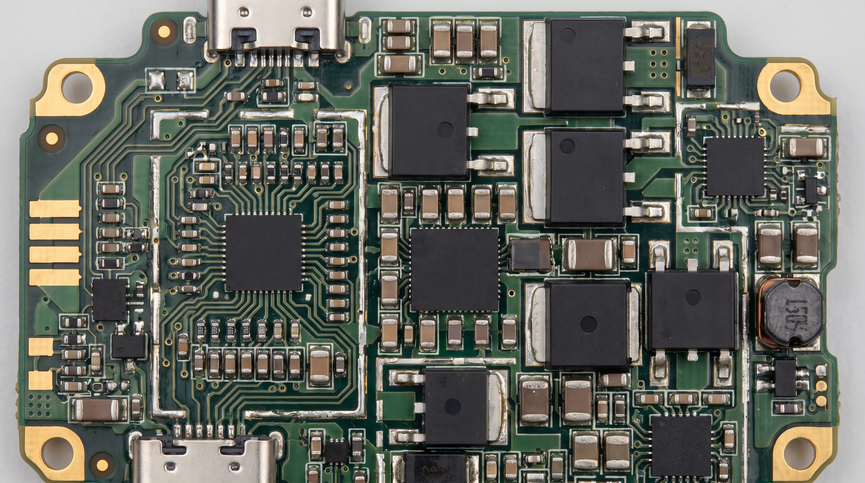
SMD capacitors are strategically placed across input filter stages, output decoupling terminals, and electromagnetic interference (EMI) bypass networks. Correct placement of an SMD capacitor in power adapter layouts ensures noise-free signal delivery to the main controller integrated circuits. Properly optimized PCB tracks keep your converter operating reliably without layout-induced performance degradation.
Why Is Proximity to ICs So Critical?
If you place these capacitors even a few millimeters too far from the switching IC, the trace inductance will render them highly ineffective. Look closely at this:
- Voltage Smoothing: Acts as local reservoirs to supply immediate current during switching.
- Parasitic Mitigation: Keeps loop areas small to prevent electromagnetic coupling.
- Signal Integrity: Protects analog control loops from receiving high-frequency digital noise.
How Do Multi-layer Layouts Benefit Filters?
Utilizing a multi-layer board allows you to shield sensitive high-impedance paths with dedicated ground planes.
- Shorter Vias: Enhances connection speed to internal reference planes.
- Enhanced Shielding: Traps electromagnetic emissions inside inner copper layers.
- Symmetrical Design: Balances thermal expansion stress during high-temperature reflow.
Key Takeaway: Positioning decoupling capacitors as close as possible to the IC pins eliminates inductive noise loops.
| Board Location | Recommended Cap Type | Typical Footprint | Primary Circuit Objective | |
|---|---|---|---|---|
| DC Input Stage | Polymer Electrolytic | 1210 or larger | Bulk energy storage & line ripple dampening | |
| Switching Node | High-Voltage MLCC | 0805 or 1206 | Snubber protection against voltage spikes | |
| Output Terminals | Low-ESR Ceramic | 0603 or 0805 | Output ripple filtering & load response |
Analyzing the correlation between physical trace length and decoupling performance reveals clear parasitic limits.
What Types of SMD Capacitor in Power Adapter Applications Are Available?
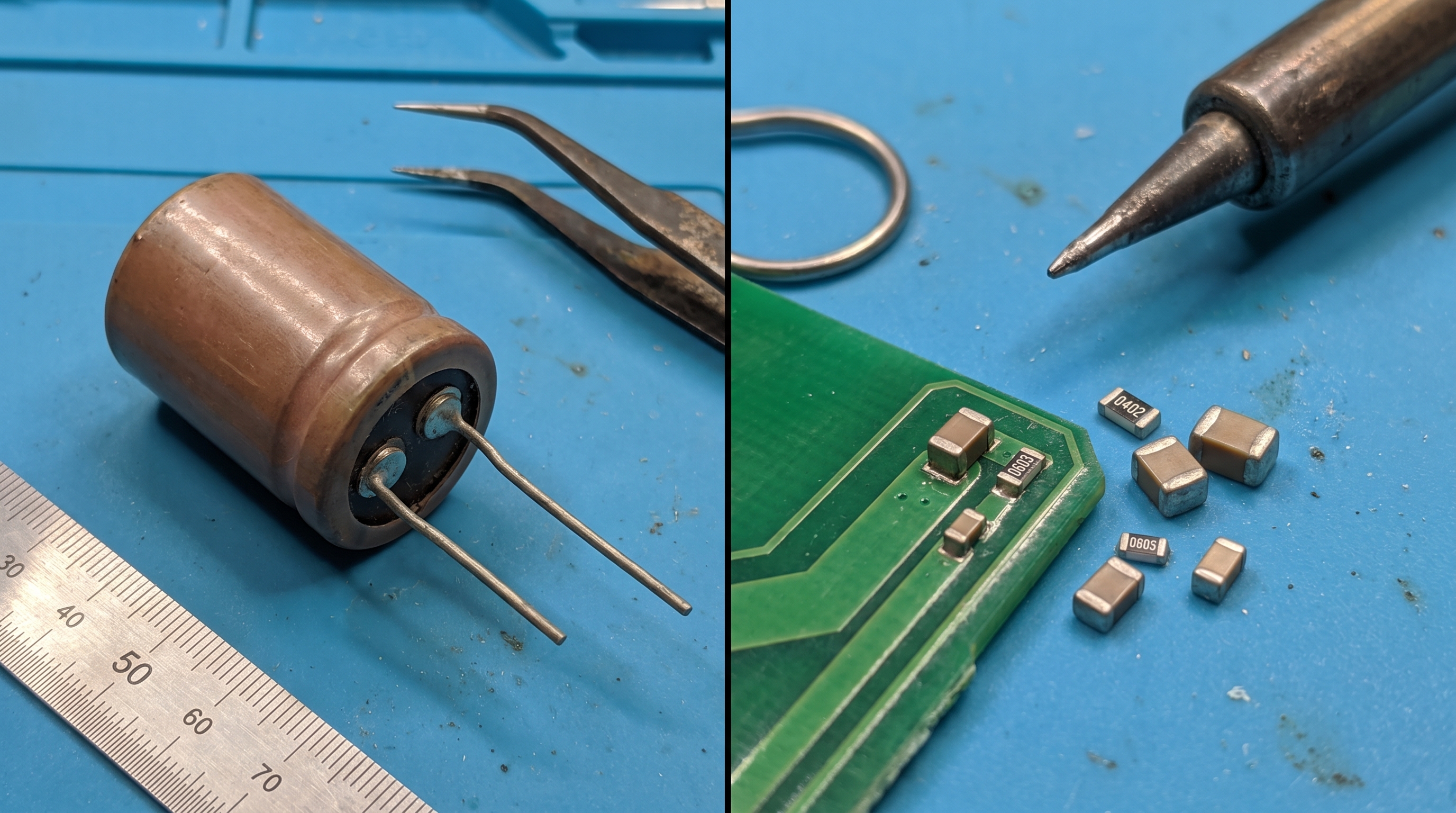
Power adapters primarily utilize multi-layer ceramic (MLCC), tantalum, and aluminum polymer SMD capacitors depending on specific circuit requirements. Each category of SMD capacitor in power adapter topologies serves a dedicated role, balancing high-capacitance filtering with voltage stability across changing temperatures. Choosing the correct formulation protects your downstream consumer devices.
When Should You Use MLCC over Tantalum?
When your project demands exceptional high-frequency filtering, MLCCs are your absolute best choice due to their non-polar construction. Let’s look closer:
- MLCC Advantages: Exceptionally high frequency performance, non-polar construction, and low unit cost.
- Tantalum Strengths: High volumetric efficiency, zero DC-bias capacitance aging, and self-healing behaviors.
- Polymer Aluminum Benefits: Extremely low ESR coupled with high bulk capacitance ratings.
Which Dielectric Yields the Best Stability?
If your power adapter operates in challenging thermal environments, choosing the correct ceramic dielectric is vital.
- Class-I (C0G/NP0): Offers zero capacitance drift over the entire operating temperature range.
- Class-II (X7R): Delivers excellent volumetric efficiency with minimal temperature-based variations.
- Class-III (Y5V): Sacrifices stability for maximum capacitance but suffers from huge thermal drops.
Key Takeaway: Class-I dielectrics provide absolute thermal stability, while Class-II materials offer maximum capacitance density.
| Dielectric Type | Temperature Range | Capacitance Drift | Primary Usage Scenario | |
|---|---|---|---|---|
| C0G / NP0 | -55°C to +125°C | ±30 ppm/°C (Ultra-stable) | Precision timing circuits | |
| X7R | -55°C to +125°C | ±15% (Highly stable) | AC bypass and noise filtering | |
| Y5V | -30°C to +85°C | +22% to -82% (Low stability) | General decoupling loops |
Evaluating standard class-II ceramic dielectrics reveals how temperature shifts alter overall circuit capacitance.
How Does an SMD Capacitor in Power Adapter Design Reduce Noise?
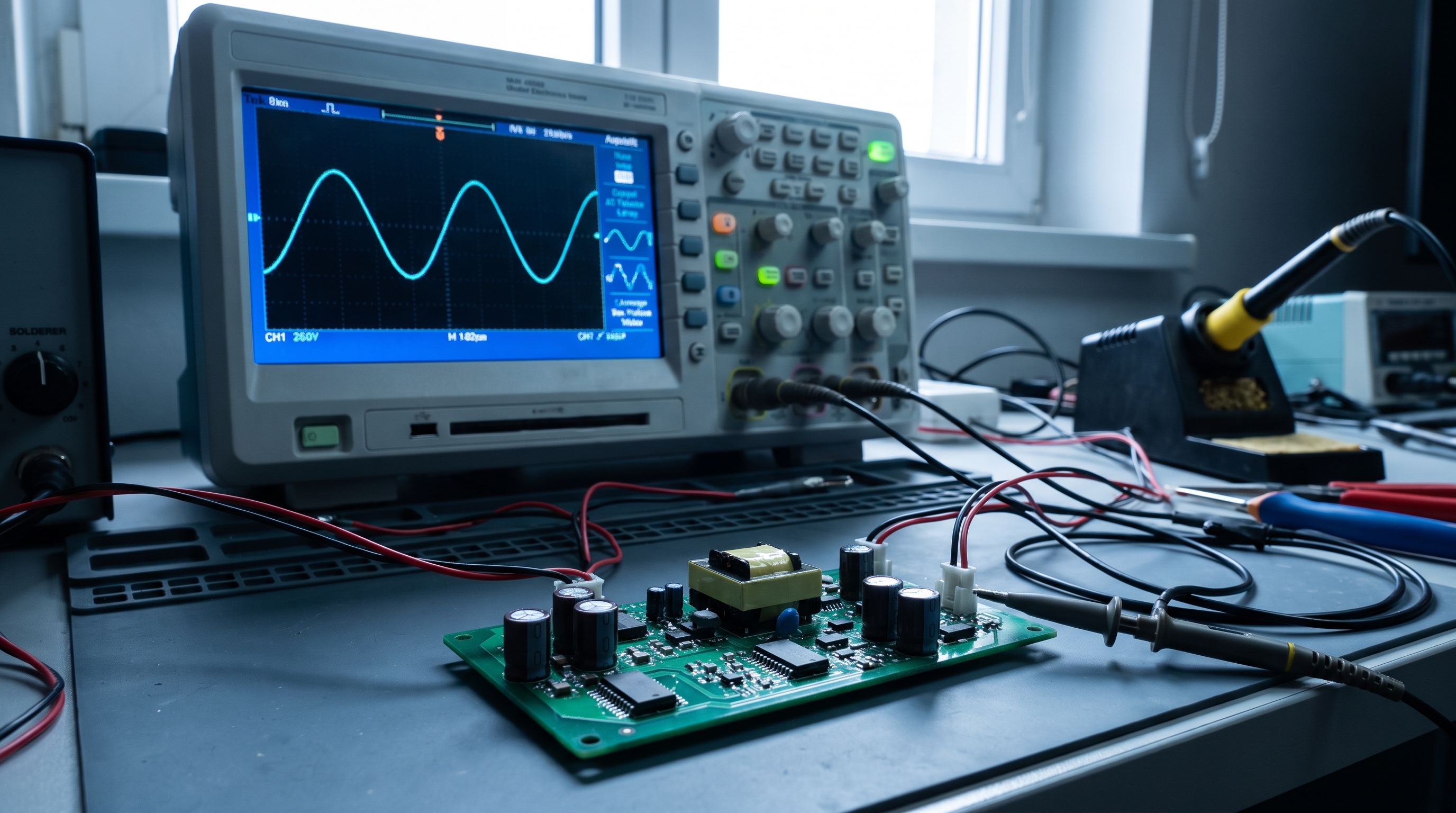
SMD capacitors reduce noise by creating low-impedance shunt paths that direct high-frequency AC interference straight to the ground plane. Properly deploying an SMD capacitor in power adapter switching networks prevents harmful EMI from feeding back into your local power lines or disturbing nearby wireless devices. This filtering action ensures complete compliance with global electromagnetic standards.
How Does AC Ripple Shunting Work?
When switching transistors turn on and off at frequencies exceeding 100 kHz, you need a component that allows AC noise to escape while blocking DC. Think about it:
- Impedance Division: Creates a division path where AC noise is selectively attenuated.
- High-Frequency Attenuation: Blocks switching spikes from propagating to the output line.
- Clean DC Reference: Establishes a highly stable voltage base for downstream components.
Can Active Filtering Outperform Passive SMDs?
While active filtering is powerful, you will find that passive SMD capacitors remain the most cost-effective and reliable method for high-frequency attenuation.
- Zero Power Consumed: Shunts noise passive-style without drawing operational bias current.
- Instantaneous Response: Acts in nanoseconds without any control loop propagation delay.
- Simpler Circuits: Eliminates complex active feedback networks to reduce development cost.
Key Takeaway: Passive SMD noise filtering offers an unbeatable balance of cost, speed, and reliability.
| Noise Source | Frequency Band | Effective Cap Type | Attenuation Rate | |
|---|---|---|---|---|
| Line Frequency (AC) | 50 Hz – 120 Hz | Aluminum Electrolytic SMD | Moderate (15dB – 25dB) | |
| Switching Harmonics | 100 kHz – 2 MHz | Medium-sized X7R MLCC | High (30dB – 45dB) | |
| EMI / RFI Spikes | 10 MHz – 100 MHz | Miniature C0G Ceramic | Extremely High (>50dB) |
Reviewing the attenuation characteristics across various noise bands highlights the necessity of multi-capacitor filtering strategies.
Why Does an SMD Capacitor in Power Adapter Reliability Matter?
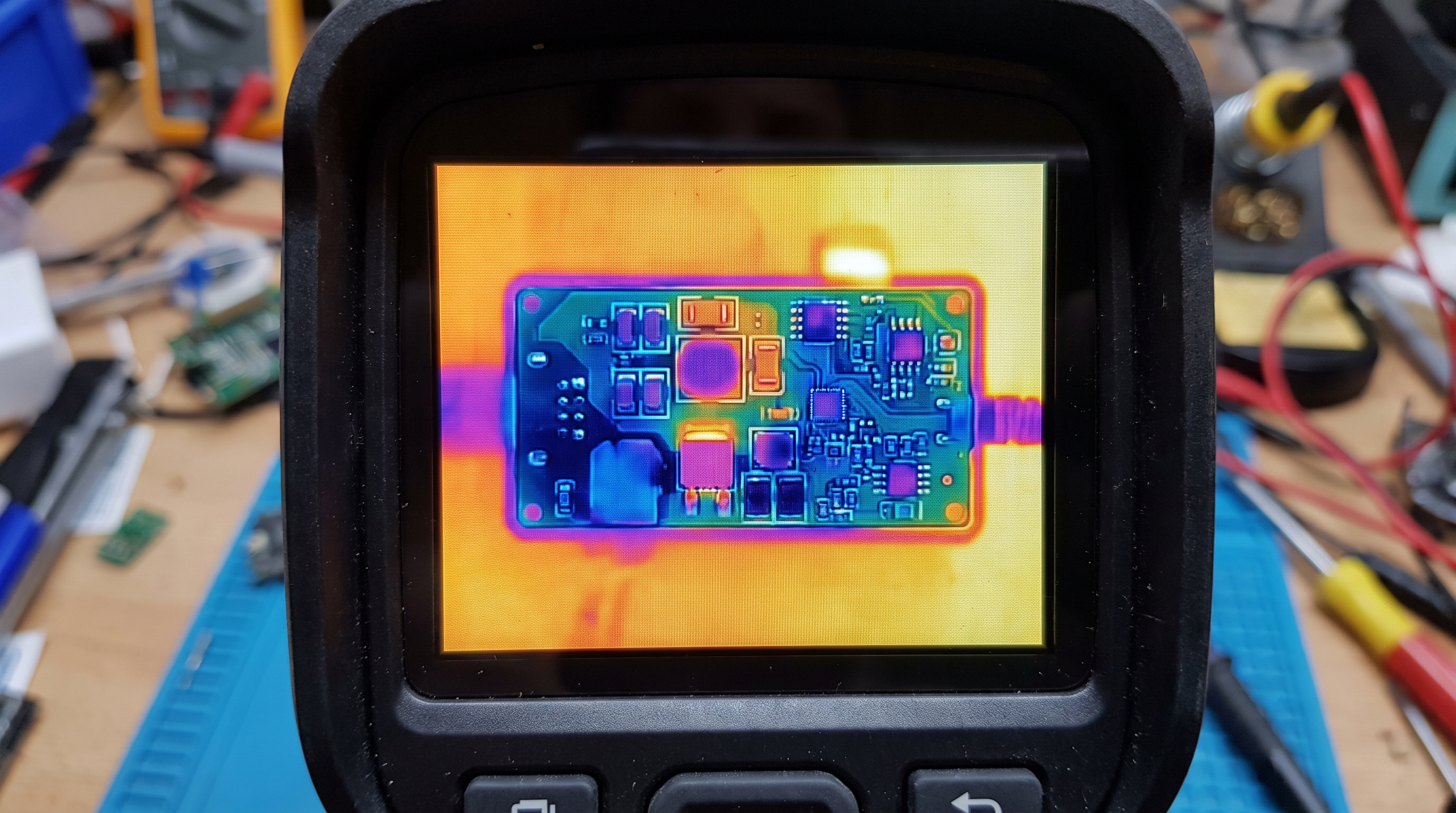
SMD capacitor reliability dictates power adapter longevity by governing the rate of wear-out mechanisms under continuous thermal and electrical stresses. The longevity of an SMD capacitor in power adapter designs directly influences the Mean Time Between Failures (MTBF) of the entire power unit. This makes premium component selection essential for critical B2B applications.
How Do Ripple Currents Degrade Capacitors?
If you subject an inferior capacitor to high-frequency ripple currents, the resulting internal power dissipation can quickly degrade the dielectric. Here is the catch:
- Self-Heating Stress: Ripple currents generate internal heat, accelerating dielectric aging.
- Dry-Out Failure: Liquid-electrolyte SMDs degrade as heat causes internal fluids to vaporize over time.
- Voltage Stress: Operating too close to rated limits triggers rapid dielectric wear.
What Is the Role of Voltage Derating?
To ensure that your adapters survive harsh operating environments, you should always build in a generous voltage margin.
- Reduced Leakage: Operating well below the maximum limit decreases self-discharge rates.
- Thermal Cushion: Offsets the temperature-induced degradation of the dielectric barrier.
- Longer MTTF: Extends the Mean Time to Failure by orders of magnitude.
Key Takeaway: Designing with a minimum 50% voltage safety margin exponentially decreases component wear-out rates.
| Applied Voltage Ratio | Estimated Component Lifespan | Wear-out Risk Profile | Recommended Application | |
|---|---|---|---|---|
| 100% of Rating | Baseline (1.0x) | High hazard level | Low-reliability consumer goods | |
| 80% of Rating | Extended (3.0x) | Moderate safety margin | Standard business hardware | |
| 50% of Rating | Maximum (10.0x+) | Ultra-low failure rate | Industrial and medical systems |
The operational life multiplier of an SMD ceramic capacitor shifts dramatically based on applied voltage ratios.
What Causes an SMD Capacitor in Power Adapter Circuits to Fail?
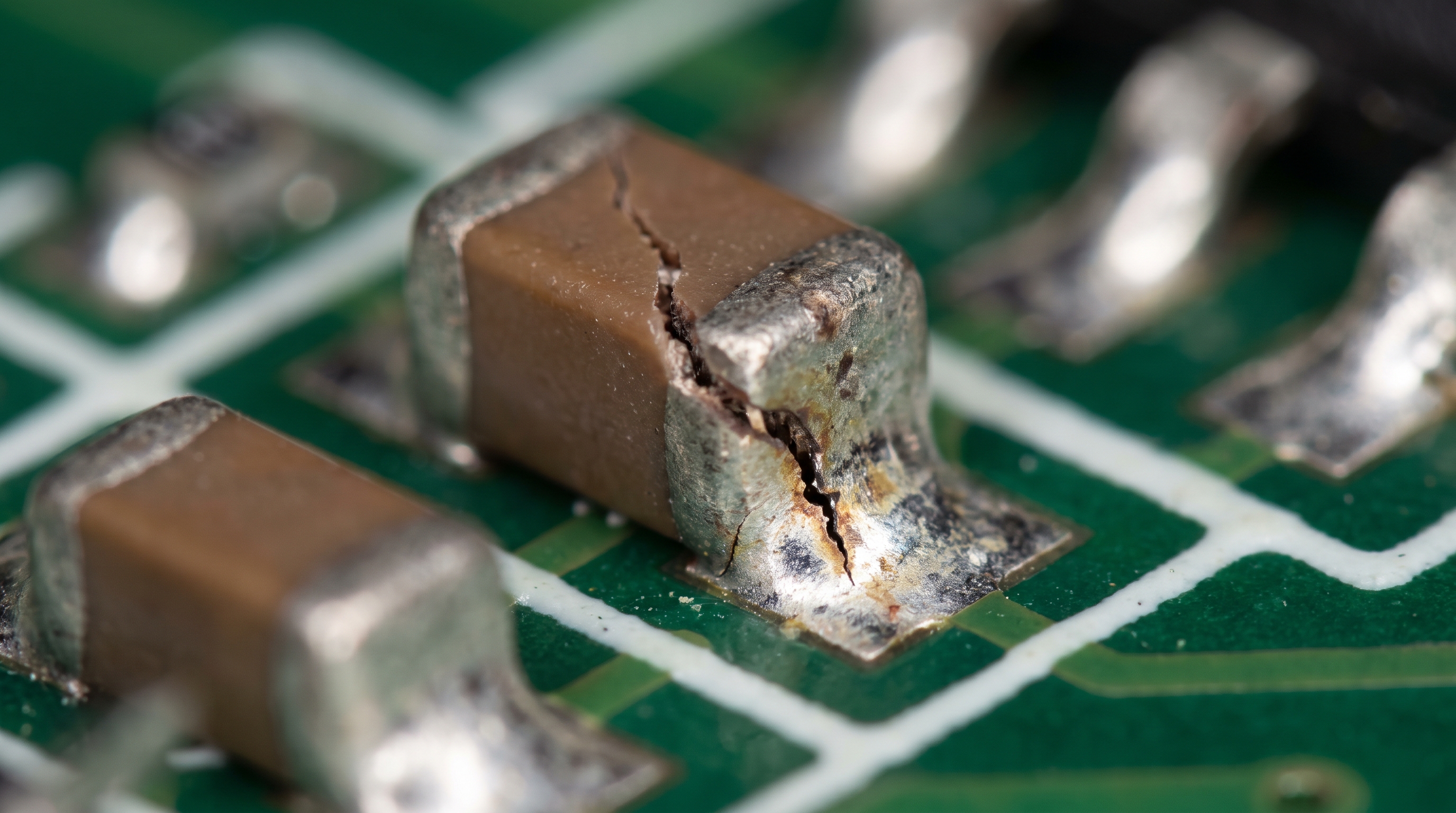
SMD capacitor failure relies on monitoring output voltage stability, checking for short circuits, and scanning for visual micro-cracking. Catching a failing SMD capacitor in power adapter circuits during automated testing prevents defective systems from slipping through to final packaging. Proper inspection steps save your customer service team from field returns.
What Visual Signs Indicate Solder Fatigue?
When you analyze mechanical stress points on your boards, you must pay close attention to terminal interfaces. Look closely at this:
- Micro-cracks: Stress lines propagating near terminal boundaries due to rapid board flexing.
- Tombstoning: A manufacturing error where a small component lifts off one pad and stands vertically.
- Solder Voids: Air bubbles trapped inside joints that weaken physical and electrical connections.
How Does Parametric Drift Cause Failure?
As capacitors age, you will notice a slow, steady loss of actual capacitance combined with a rise in ESR.
- Elevated Ripples: Reduced capacitance struggles to filter switching noise, causing voltage drops.
- Thermal Runs: Increased ESR raises operating temperatures, accelerating component degradation.
- System Instability: Downstream processors may experience spontaneous resets due to noisy rails.
Key Takeaway: Drift-related capacitance drops lead to elevated noise floors, triggering system reboots.
| Failure Mode | Electrical Signature | Primary Root Cause | Effective Preventive Step | |
|---|---|---|---|---|
| Short Circuit | 0Ω resistance | Dielectric voltage puncture | Increase voltage derating ratio | |
| Open Circuit | Infinite resistance | Thermal fusion of internal electrodes | Optimize current surge limits | |
| High ESR Drift | Elevated AC ripple output | Electrolyte loss or cracked layer | Switch to robust polymer caps |
Gradual component degradation reveals how aging dielectrics affect system-wide noise suppression.
How Should Manufacturers Select an SMD Capacitor in Power Adapter Production?
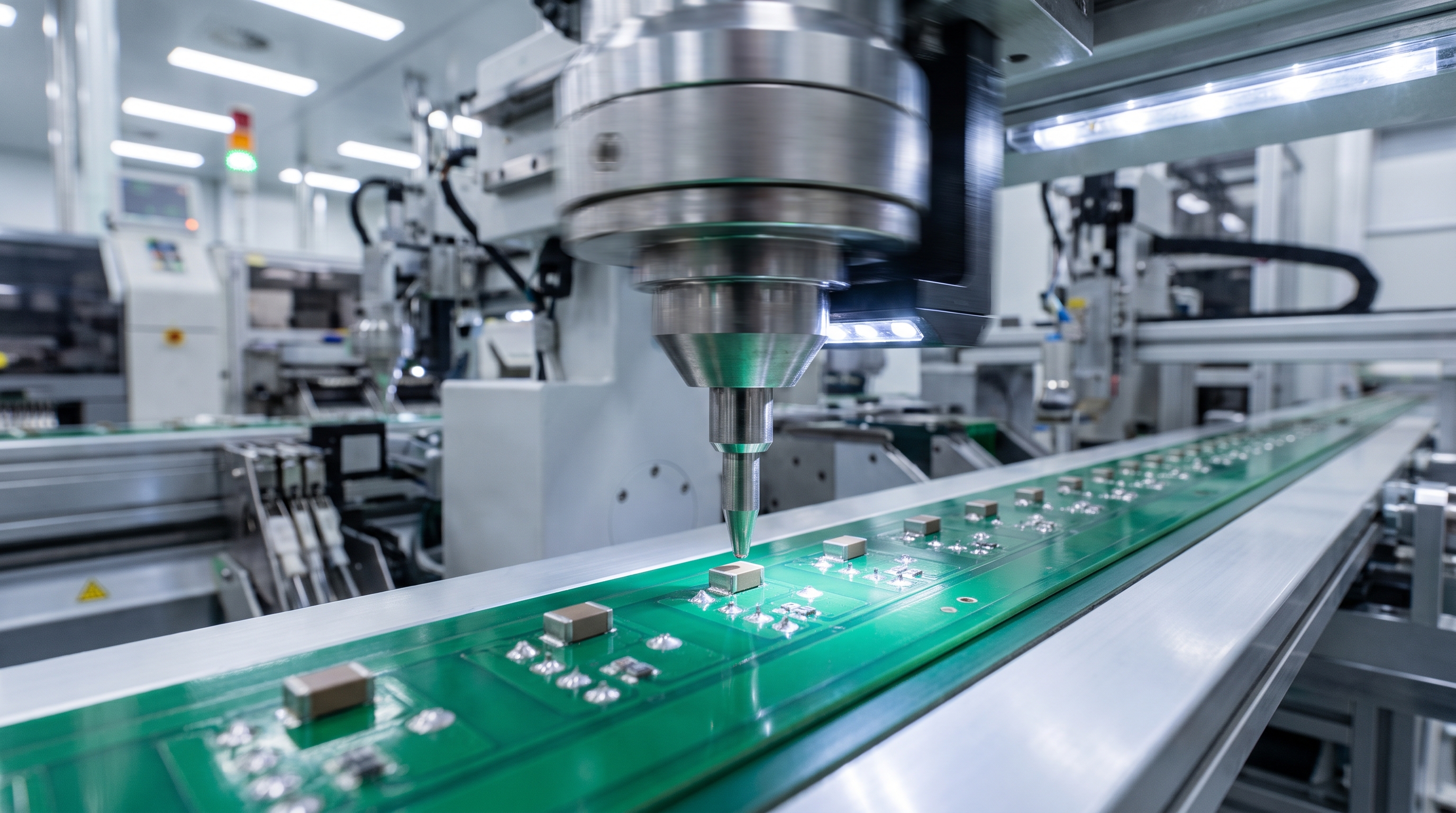
Selecting the best SMD capacitor requires matching the operating temperature, voltage overhead, capacitance requirements, and target ESR to your circuit’s load profiles. Specifying the optimal SMD capacitor in power adapter layouts prevents unstable system behavior during rapid, high-demand load transitions. Partnering with a skilled OEM manufacturer simplifies this selection process.
How Do You Calculate Required Capacitance?
To properly size your filtering capacitors, you must evaluate the converter’s peak currents and switching speed. Here is the calculation:
- Determine Ripple Budget: Establish the maximum allowable output AC ripple voltage.
- Factor in Frequency: Calculate values based on the controller’s switching frequency.
- Calculate Dynamic Load: Estimate target values using peak-to-peak output load steps.
What Role Does ESR Play in Component Choice?
If you select parts with an ESR that is too low, you might inadvertently compromise the feedback stability of your power control loop.
- Target Damping: A small amount of ESR is often helpful to prevent control loop oscillations.
- High Efficiency: Extremely low ESR is vital for maximizing power throughput in high-current paths.
- Cost Balance: Avoid over-specifying ultra-low ESR parts when standard-grade components meet the design criteria.
Key Takeaway: Selecting ultra-low ESR parts improves energy conversion but can affect control loop stability.
| Component Family | ESR Class | Typical Cost Profile | Recommended Duty Cycle Location | |
|---|---|---|---|---|
| Standard MLCC | Ultra-low (0.5 – 5 mΩ) | Economical | High-frequency input/output bypass | |
| Polymer Tantalum | Low (5 – 25 mΩ) | Premium | High-density bulk filter bank | |
| SMD Electrolytic | Moderate (0.1 – 2 Ω) | Budget-friendly | Main line-frequency filter |
The balance between component ESR and ripple voltage attenuation profiles is detailed in the table below.
How Can Buyers Evaluate SMD Capacitor in Power Adapter Quality?
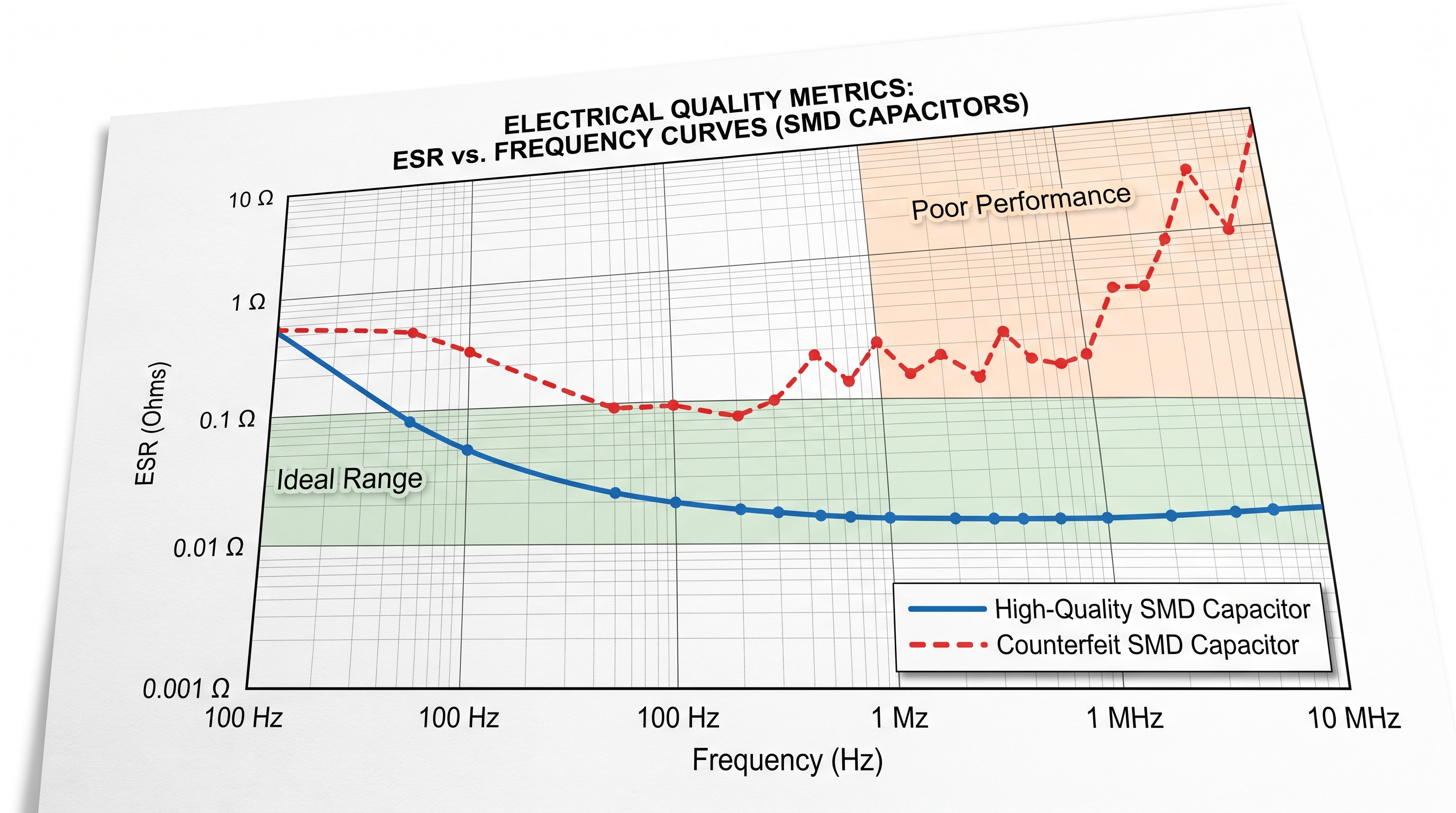
Buyers can evaluate SMD capacitor quality by inspecting certified test laboratory reports, verifying equivalent series resistance curves, and auditing manufacturing safety certifications. Assessing an SMD capacitor in power adapter shipments helps protect you from importing counterfeit or poorly structured components. This rigorous verification step guarantees that your high-power systems are safe for consumer markets.
What Tests Verify Actual Lifetime Claims?
When you want to prove that a supplier is delivering durable hardware, you should request their accelerated life testing data. Here is what you need:
- High-Temperature Burn-In: Subjects components to intense thermal stress for hundreds of hours.
- Humidity Exposure: Verifies that the outer encapsulation prevents moisture from penetrating the dielectric.
- Temperature Cycling: Forces the board through extreme thermal transitions to reveal solder joint fatigue.
Why Is Traceability Important in Sourcing?
If you cannot verify the exact manufacturing origin of your capacitors, you run a high risk of utilizing sub-standard materials.
- Batch Consistency: Ensures that every shipment matches the original certified design sample.
- Counterfeit Detection: Protects your supply chain from mixed or recycled electronic components.
- Root-Cause Analysis: Allows engineers to track any field defects back to the exact production batch.
Key Takeaway: Comprehensive component traceability protects your supply chain from the catastrophic failure risks of counterfeit components.
| Quality Metric | High-Quality Standard | Low-Quality Indicator | Primary Risk to Buyer | |
|---|---|---|---|---|
| ESR Stability | Constant low flat line | Spikes upward with age | Severe heat generation and system shutdown | |
| Capacitance Tolerance | Narrow deviation (±10%) | Wide variations (±30%+) | Inadequate filtering and unstable voltage output | |
| Insulation Resistance | Over 10 GΩ | Under 100 MΩ | High leakage currents and eventual short circuits |
Analyzing these critical quality metrics reveals how high-precision manufacturing directly prevents hardware failures in the field.
Conclusion: Sourcing Reliable Charging Solutions
Designing high-efficiency power adapters requires a careful balance of micro-electronics engineering and rigorous quality control. For over 20 years, Merryking Power has operated as a leading OEM/ODM manufacturer, utilizing state-of-the-art production lines and high-precision SMT assembly machines to build world-class power adapters. By selecting premium, certified components, we ensure that every adapter delivers rock-solid voltage stability and long-term hardware reliability.
If you want to optimize your hardware projects with high-reliability power solutions, contact us today to schedule a direct consultation with our engineering team. Let us show you how our professional custom designs can elevate your products, lower your failure rates, and enhance your competitive edge in the global marketplace.
Frequently Asked Questions
Can I substitute a radial leaded capacitor with an SMD type during a redesign?
Yes, you can. However, you must carefully evaluate the copper pad layout, maximum heat ratings, and the potential impact of mechanical flexing on the PCB. Because SMD capacitors are rigid, any physical board flexing during assembly or drop-tests can place direct mechanical stress on the solder joints, potentially leading to open circuits or short-circuit failures.
What’s the best way to prevent ceramic capacitor micro-cracking during assembly?
The best way is to control board flex. Position your SMD capacitors away from high-stress areas (such as mounting holes or V-groove scoring lines) and run routine checks on your reflow solder temperatures. Ensuring that the SMT assembly line is precisely calibrated prevents thermal shocks and board twisting, which are the main causes of physical micro-cracking.
How does a capacitor’s DC bias effect change its usable capacitance?
Usable capacitance decreases under DC bias. In Class-II ceramic capacitors (such as X7R), applying a DC voltage can reduce the actual capacitance by 30% to 60%, requiring you to build in extra component overhead. To prevent unexpected voltage ripple increases, you must select capacitors with a higher voltage rating than your circuit’s operating level.
Can automated optical inspection (AOI) catch invisible capacitor cracks?
No, standard AOI cannot. While AOI is highly effective at identifying misalignments, solder bridges, and lifted leads, detecting deep internal micro-cracks requires specialized testing like acoustic microscopy or X-ray imaging. Therefore, prevention through optimized layout rules and careful thermal profiling remains the most reliable strategy.
What is the typical lead time for custom OEM adapter production runs?
The standard lead time is 4 to 6 weeks. This window covers component procurement, PCB production, quality checks, and final safety certification reviews. Working with an integrated partner like Merryking Power helps streamline this timeline by utilizing pre-vetted components and automated manufacturing techniques.