Isolation voltage in power supplies is the maximum electrical voltage that can be applied between the input and output circuits without breaching the physical insulation barrier. Imagine a sudden high-voltage power spike striking your facility’s electrical grid. Without a protective safeguard, this transient spike will instantly destroy sensitive downstream controllers, risking catastrophic hardware downtime and severe safety hazards for your operators. Choosing a certified isolation voltage in power supplies provides the ultimate protective barrier that isolates destructive input surges from your low-voltage output lines.
This electrical rating represents the physical capability of non-conductive insulation materials to block direct current flow while allowing power to transfer safely. Typically expressed in Volts AC (VAC) or Volts DC (VDC), it establishes the boundary limits of your system’s safety margin. Higher ratings mean your electrical architecture is engineered to handle extreme electrical stress. Let’s look closer at how this mechanism functions in real-world setups.
How Do Primary and Secondary Circuits Separate?
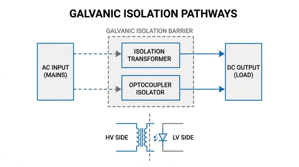
Think about it: how does electricity cross a physical gap without direct wire connections? Designers achieve this critical separation by establishing distinct primary and secondary circuits inside the power unit. The primary circuit handles the hazardous AC grid voltage, while the secondary circuit delivers clean, low-voltage DC power to your devices. This careful segmentation ensures that a high-voltage failure on one side cannot easily propagate to the other.
- Primary Circuit: High-voltage input side connected directly to the AC mains supply.
- Secondary Circuit: Low-voltage output side feeding sensitive downstream electronics.
- Galvanic Barrier: Non-conductive isolation zone preventing current flow between sides.
By ensuring no copper-to-copper contact exists, you prevent high voltage from finding an accidental path to the output terminals. This clean layout is vital for maintaining system integrity and keeping your delicate microchips completely unharmed during grid instability. You can trust that this physical barrier works silently to keep your daily operations safe. It acts as an active shield protecting your business from sudden component failures.
Key Takeaway: Separating primary and secondary circuits creates a physical boundary that stops destructive high-voltage surges from ever reaching your low-voltage hardware.
Why Is Isolation Voltage in Power Supplies Important for Safety?
Isolation voltage in power supplies is crucial for safety because it acts as an impenetrable barrier that prevents hazardous high-voltage mains electricity from reaching metal enclosures or user-accessible outputs. Without this critical protection, any internal component breakdown could instantly energize an external casing and create a lethal environment for operators. Specifying a high isolation voltage in power supplies guarantees that hazardous electrical energy remains securely contained inside the primary circuit. This level of defense is the primary engineering safeguard designed to save human lives in industrial and commercial workspaces.
In addition to protecting human life, high safety thresholds preserve high-value equipment assets from expensive destructive failures. A single voltage breakthrough can easily cascade through your local network, ruining industrial PLCs, communication switches, and digital sensor hubs. By choosing adapters with robust safety barriers, you build a reliable electrical firewall. This defensive layer ensures your business avoids costly downtime and liability concerns.
Can High Safety Ratings Save Your Infrastructure?
Let’s dig deeper: when you analyze safety, you are looking at risk mitigation for both personnel and expensive hardware. If a catastrophic lightning strike hits the power grid, your power adapter’s insulation must absorb that energy. Sourcing certified power modules prevents dangerous voltage levels from bridging to the output connectors. Investing in premium safety ratings directly reduces the risk of equipment fires and operational interruptions.
- User Safety: Eliminates the risk of direct human contact with dangerous grid potentials.
- Hardware Defense: Prevents high-voltage leakage from frying connected microcontrollers and sensors.
- Fire Prevention: Reduces thermal buildup and localized electrical arcing during grid faults.
When you deploy heavy machinery, safety is not an area where you can afford to cut corners. High-quality isolation ensures that minor grid anomalies remain minor events rather than multi-million dollar operational disasters. This proactive design focus lets your engineering team build systems with complete confidence. You will save valuable resources by preventing major equipment damage before it can start.
Key Takeaway: High safety ratings protect both human lives and your physical infrastructure from catastrophic high-voltage system faults.
| Safety Level | Isolation Voltage (Typical) | Principal Benefit | Common Application | |
|---|---|---|---|---|
| Basic | 1,500 VAC | Basic component shielding | Low-cost office electronics | |
| Double | 3,000 VAC | Enhanced user protection | Industrial and commercial devices | |
| Reinforced | 4,000 VAC | Maximum operator safety | Medical and extreme environment systems |
This standard data highlights why aligning your equipment’s isolation levels with professional safety benchmarks is vital for long-term protection.
How Does Isolation Voltage in Power Supplies Prevent Electric Shock?
Isolation voltage in power supplies prevents electric shock by completely breaking the physical electrical return path between high-voltage inputs and any user-accessible output terminals. Under standard operating conditions, electrical current must form a closed loop through the ground or a human body to cause a shock. A highly rated isolation voltage in power supplies ensures that no current can bridge this physical gap, making it impossible for a user to complete the circuit. This elegant design principle neutralizes the threat of electrical shock even when you touch a powered device’s metal chassis.
To achieve this, engineers rely on physical space and non-conductive barriers on the circuit board. By ensuring that high and low voltages never share a direct copper pathway, you eliminate the risk of electric current choosing a human path. This structural strategy works silently and continuously to shield you from the grid’s dangerous potential. Let’s look at the specific design features that keep you isolated.
What Mechanisms Keep Current Away From You?
Here is why: electricity is lazy and will always seek the path of least resistance to the ground. By using magnetic and optical coupling techniques, you create an electrical dead-end for dangerous current while letting power flow smoothly. This means you can interact with your controllers without any fear of static or shock. It completely eliminates the physical path that current would need to travel through your body.
- Magnetic Isolation: Transformers pass energy through magnetic fields without touching copper-to-copper.
- Optical Coupling: Control signals use infrared light beams to bridge high-voltage splits safely.
- Physical Gaps: Printed circuit boards maintain strict physical distances between different voltage planes.
Understanding these internal pathways helps you select the correct hardware for your specific workspace requirements. When you use properly insulated adapters, you guarantee that hazardous current remains safely isolated behind physical walls. This structural safeguard is essential for any equipment operated by human hands. It keeps your field technicians safe during routine maintenance tasks.
Key Takeaway: Precise non-conductive gaps and coupling methods physically stop electrical current from traveling through the user’s body.
| Protective Element | Physical Isolation Method | Effectiveness Level | Primary Failure Risk | |
|---|---|---|---|---|
| Magnetic Transformer | Inductive coupling via magnetic core | Extremely High | Overheating & coil insulation wear | |
| Optocoupler | Optical link using infrared light | Maximum | High-temperature degradation | |
| PCB Creepage/Clearance | Air gaps and board layout spacing | Very High | Humidity and dust buildup |
Reviewing these protective elements shows how multiple layers of defense work together to eliminate shock hazards in your system.
What Factors Affect Isolation Voltage in Power Supplies?
Several critical factors affect isolation voltage in power supplies, including environmental humidity, airborne dust contamination, physical circuit board layout spacing, and altitude. When your equipment operates in real-world conditions, these external elements can degrade the dielectric strength of solid insulators and air gaps over time. Standard ratings for the isolation voltage in power supplies are calculated under clean, dry laboratory conditions, but harsh environments alter these baselines. This means that environmental factors must be heavily accounted for during your initial system integration process.
For instance, high altitude lowers air density, which makes it much easier for high-voltage electricity to ionize the air and spark across physical gaps. Similarly, moisture and conductive dust can settle on the PCB, creating virtual bridges that slowly bypass your safety zones. Understanding these environmental vulnerabilities ensures you choose hardware that will not degrade prematurely in your target application. Let’s examine how layout dimensions affect these parameters.
How Do Spacing Gaps Protect Your System?
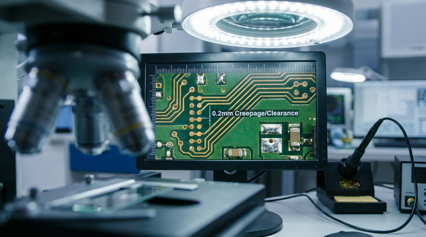
Let’s dig deeper: when you lay out high-voltage circuit traces, physical distance is your absolute best friend. Electrical standards specify strict minimum dimensions for creepage and clearance to prevent arcing across the board surface or through the air. If these distances are too small, high-voltage spikes can jump right over your safety barriers. This makes layout precision one of the most critical aspects of power supply design.
- Creepage Distance: The shortest path along the surface of the insulation material between conductive parts.
- Clearance Distance: The shortest path through the air between conductive points on the board.
- Altitude De-rating: Adjustments made to physical spacing to compensate for thinner air at high elevations.
By maintaining these strict physical limits, you prevent environmental contaminants from compromising your unit’s safety barrier. Sourcing premium power units ensures that these dimensions are carefully maintained throughout the product’s lifespan. You will experience fewer field failures when your hardware is built to withstand high pollution environments. It is a smart engineering step that yields long-term operational success.
Key Takeaway: Adequate clearance and creepage spacing are crucial to keeping your power system immune to environmental degradation.
| Environmental Variable | Impact on Isolation Barrier | Best Design Mitigation | Recommended Standard | |
|---|---|---|---|---|
| High Humidity | Increases risk of surface tracking | Apply conformal PCB coatings | Pollution Degree 2/3 | |
| High Altitude (>2000m) | Reduces air dielectric strength | Increase physical clearance gaps | IEC altitude de-rating curves | |
| Conductive Dust | Creates conductive paths on board | Use fully sealed IP-rated enclosures | Pollution Degree 3 guidelines |
This comparison highlights why you must evaluate your site’s physical environment before selecting power adapters.
How Is Isolation Voltage in Power Supplies Tested?
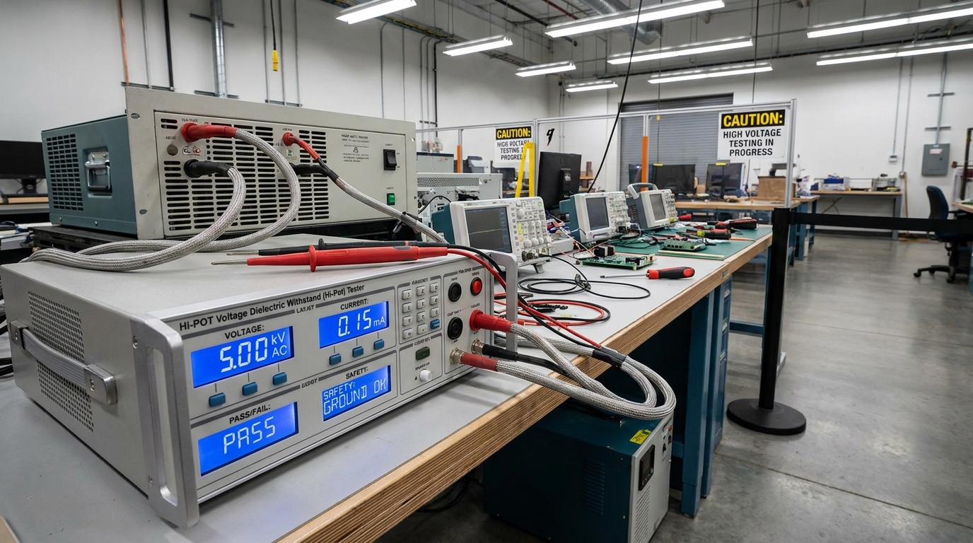
Isolation voltage in power supplies is tested by applying a high-potential electrical voltage across the safety barrier to verify that no dielectric breakdown or excessive leakage current occurs. This quality-assurance testing process, commonly known as a Hi-Pot (High Potential) test, subjects the unit to extreme electrical stress for a specific duration. During factory compliance, the isolation voltage in power supplies must withstand this intense testing voltage without any sparks or insulation failure. This rigorous validation ensures that every unit leaving the assembly line is completely safe for field deployment.
Beyond Hi-Pot testing, manufacturers perform insulation resistance and leakage current measurements to verify the barrier’s efficiency under normal load. These tests confirm that only minuscule, safe amounts of stray micro-amperes can ever pass through your system. By choosing fully tested power modules, you protect your system from latent manufacturing defects. Let us explore how these testing protocols are structured.
What Happens During Factory Safety Verification?
Think about it: how do you know your power supply will handle a major grid surge safely? Factory technicians use specialized automated testing stations to run highly calibrated electrical diagnostics on every single production batch. This continuous inspection ensures that potential weak points are caught before they ever reach your facility. It provides an objective, evidence-based confirmation of the unit’s physical integrity.
- Voltage Ramp-Up: Slowly increasing the test voltage to avoid damaging the unit with sudden inductive spikes.
- Dwell Time: Holding the maximum peak voltage for 60 seconds during regulatory laboratory certification.
- Leakage Threshold: Monitoring current flow to ensure it remains well within safe micro-amp limits.
When you deploy certified hardware, you gain complete confidence that your system has survived these intense simulated failures. This proactive testing regimen is what separates cheap generic power adapters from robust industrial-grade solutions. You will avoid the headaches of early field failures by choosing thoroughly validated hardware. It is the easiest way to guarantee safety in your next system deployment.
Key Takeaway: Rigorous factory testing guarantees that your power adapter’s insulation barrier is free from manufacturing flaws and fully ready for industrial duty.
| Verification Test | Testing Objective | Typical Stress Level | Target Performance Metric | |
|---|---|---|---|---|
| Hi-Pot Test | Detects dielectric breakdown | 1,500 – 4,000 VAC | Zero arcing or insulation breakdown | |
| Insulation Resistance | Measures ohmic resistance | 500 VDC | Resistance greater than 100 Mega-ohms | |
| Leakage Current | Measures stray leakage | Operating AC Voltage | Leakage remains under 100 to 500 micro-amps |
These testing parameters demonstrate the strict quality controls required to ensure absolute safety for your connected electronics.
Which Industries Require High Isolation Voltage in Power Supplies?
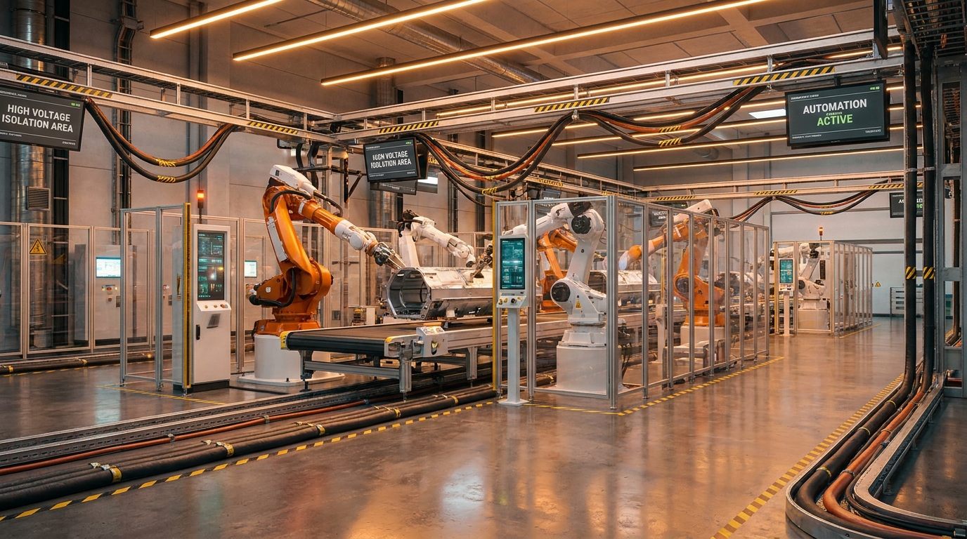
Medical technology, heavy industrial automation, telecommunications, and aerospace systems require high isolation voltage in power supplies due to the critical risks of human injury or massive system downtime in these sectors. For instance, diagnostic medical equipment often connects directly to vulnerable patients, necessitating ultra-low leakage currents and double safety barriers. In these demanding situations, a premium isolation voltage in power supplies is a non-negotiable safety requirement to prevent micro-shocks. Similarly, automated factories operate heavy inductive machinery that regularly feeds dangerous surges back into local power lines.
In telecommunication centers, power supplies must protect expensive network routers and switches from external grid surges and lightning strikes. A single power failure in these hubs can immediately disrupt vital communications for thousands of users. By matching your specific industry requirements with high-isolation power architectures, you secure your operations against unpredictable power grids. Let us examine the unique safety profiles of these different sectors.
Where Is Premium Safety Most Critical?
Here is why: some environments are inherently more hazardous and demanding than standard commercial offices. If you operate electronic equipment in a wet hospital ward or near high-power industrial motors, the safety stakes are incredibly high. Selecting the correct safety margin ensures you maintain complete compliance with stringent industry regulations. It acts as a primary engineering control designed to mitigate high-voltage shock risks.
- Healthcare Units: Demands the highest safety standards to protect patients from tiny, dangerous leakage currents.
- Automated Factories: Requires robust shielding to isolate sensitive PLC systems from heavy motor electrical noise.
- Telecom Facilities: Focuses on surge protection to maintain continuous data line uptime during bad weather.
By matching your industry’s specific challenges with certified components, you ensure your project’s safety and regulatory success. This targeted approach prevents costly system re-designs and ensures long-term operational peace of mind. You can expand your market reach by choosing adapters that carry all necessary global safety credentials. It represents a highly strategic investment in your brand’s technological reputation.
Key Takeaway: High isolation is absolutely essential for healthcare, factory automation, and communication networks where failure carries severe human or financial consequences.
| Industry Sector | Critical Safety Risk | Core Regulatory Standard | Typical Isolation Target | |
|---|---|---|---|---|
| Medical Technology | Direct patient electric shock | IEC 60601-1 (2xMOPP) | 4,000 VAC (Double/Reinforced) | |
| Industrial Automation | Ground loops and grid surges | IEC 61010-1 / IEC 62368-1 | 3,000 VAC | |
| ICT & Telecom | Data corruption & line surges | IEC 62368-1 | 1,500 VAC |
This industry comparison illustrates how different operational environments dictate the level of insulation performance you need.
How Do Safety Standards Regulate Isolation Voltage in Power Supplies?
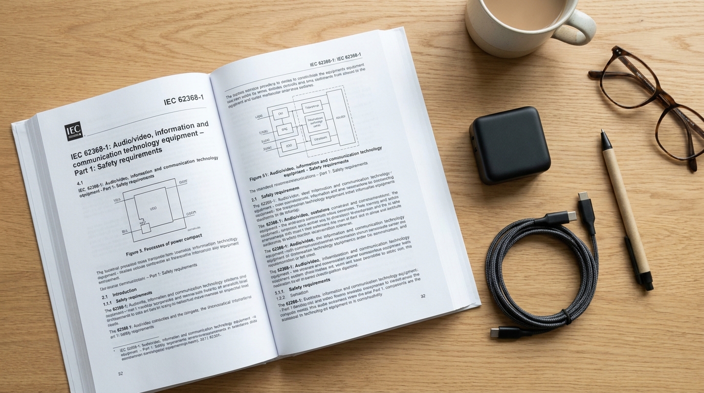
Safety standards regulate isolation voltage in power supplies by defining mandatory minimum dielectric insulation levels, creepage distances, and safety-testing methods based on the specific hazard risks of the target application. International bodies like the IEC and UL classify electrical equipment into different hazard categories to ensure appropriate operator and patient protection. To comply with these strict rules, the isolation voltage in power supplies must meet or exceed the predefined safety values established for each product type. This rigorous standardization makes it easy for you to verify safety compliance when sourcing global hardware.
For example, the modern IEC 62368-1 standard utilizes a hazard-based model that proactively designs out risk for IT and AV products. In contrast, the medical IEC 60601-1 standard mandates strict “Means of Patient Protection” (MOPP) to prevent tiny leakage currents. By sourcing certified power adapters, you align your product with these internationally recognized safety baselines. Let us look at how these classifications protect your workspace.
What Are the Standard Levels of Protection?
Let’s dig deeper: when you review safety documentation, you will see terms like MOOP and MOPP used frequently. These acronyms define whether the insulation is designed to protect general machine operators or vulnerable medical patients. Knowing the difference helps you choose the correct level of safety redundancy for your project. It ensures that your selected power modules align perfectly with international compliance laws.
- Means of Operator Protection (MOOP): Standard safety barriers designed to protect workers in industrial and office environments.
- Means of Patient Protection (MOPP): Strict, high-performance insulation designed to protect patients in contact with medical devices.
- Double Insulation: Utilizing two separate physical layers of independent insulation to eliminate the need for a safety ground.
When you understand these standardized categories, you can make highly informed purchasing decisions for your engineering team. Adhering to these global guidelines keeps your business safe from regulatory penalties and product liability claims. You can confidently deploy your products in any major international market without safety concerns. It streamlines your export processes and simplifies your system certification.
Key Takeaway: Universal safety standards provide clear, hazard-based templates that ensure your power adapters are engineered to prevent real-world injury.
| Safety Classification | Core Testing Target | Main Target Audience | Required Insulation Level | |
|---|---|---|---|---|
| 1 x MOOP | 1,500 VAC | Standard equipment operators | Basic single-layer insulation | |
| 2 x MOOP | 3,000 VAC | Industrial equipment operators | Double / Reinforced insulation | |
| 2 x MOPP | 4,000 VAC | High-risk medical patients | Maximum reinforced isolation barrier |
This regulatory matrix clearly demonstrates why selecting certified adapters is critical for maintaining high compliance standards in your system.
What Materials Improve Isolation Voltage in Power Supplies?
Advanced dielectric materials, including high-grade polyimides, technical ceramics, specialized silicone gels, and flame-retardant polymers, improve isolation voltage in power supplies by providing superior resistance to electrical breakdown. These modern insulation media are engineered to withstand massive voltage potentials without suffering from physical or chemical degradation. Improving the isolation voltage in power supplies using these top-tier materials allows manufacturers to maintain tight physical dimensions while enhancing safety. By selecting premium raw materials, developers can build compact adapters that do not compromise on safety ratings.
Inside transformers, triple-insulated wiring replaces traditional enamel-coated wire to provide three independent physical layers of protection against winding shorts. Optocouplers utilize high-dielectric silicone gel to fill internal air spaces and prevent hazardous arcing between light emitters and receivers. Using these top-tier components ensures your power system remains incredibly resilient under high electrical loads. Let us examine the characteristics of these modern insulating materials.
How Does Material Science Protect Systems?
Think about it: how do you keep electrical currents confined to microscopic paths when handling thousands of volts? High-performance engineering plastics like PBT and polyimide films are designed specifically to resist tracking and chemical wear over decades of operation. This material integrity is what keeps your power supply functioning reliably year after year. It prevents the slow structural decay that often plagues lower-quality components.
- Polyimide (Kapton): Extremely high dielectric strength and thermal stability for transformer tape insulation.
- Triple-Insulated Wire: Three separate extruded protective layers that eliminate the need for bulky transformer margins.
- PBT Polyester: Robust material used to construct highly rigid transformer bobbins and structural internal frames.
When you choose components manufactured with these advanced materials, you invest in long-term safety and performance. This quality focus ensures your equipment is protected against the thermal and physical stresses of continuous field use. You can trust that your devices will continue to run safely even under harsh, high-temperature conditions. It is a critical design advantage that pays dividends over time.
Key Takeaway: Sourcing power supplies built with advanced dielectric polymers and triple-insulated wire prevents early insulation failure and physical breakdown.
| Insulating Medium | Approximate Dielectric Strength | Peak Thermal Limit | Primary Application | |
|---|---|---|---|---|
| Polyimide Film | 240 kV/mm | Up to 400°C | Transformer wire winding wraps & sensor barriers | |
| FR-4 Epoxy Glass | 30 kV/mm | Up to 130°C | Printed circuit board (PCB) substrate layers | |
| PBT Engineering Plastic | 20 kV/mm | Up to 150°C | Transformer bobbins and structural separator brackets |
This physical data demonstrates why material choice directly dictates the strength and compact size of modern safety barriers.
How Isolation Voltage in Power Supplies Affects Product Reliability?

Isolation voltage in power supplies directly affects product reliability by reducing dielectric wear, preventing thermal hot spots, and protecting sensitive control circuitry from destructive high-voltage switching transients. When you design a system with a healthy safety margin, the internal insulating materials operate far below their absolute physical limits. This low electrical stress dramatically slows down the natural aging process of PCB substrates and transformers. By specifying a generous isolation voltage in power supplies, you build a durable system that stands up to continuous field stress.
In contrast, cheap power units with minimal isolation margins are prone to localized high-voltage arcing and gradual insulation breakdown. Over time, these micro-faults create leakage paths that degrade signal integrity and cause intermittent system resets. Over-specifying your insulation limits ensures your critical systems avoid sudden field failures. Let’s explore how generous isolation margins translate directly into product lifespan.
Why Do Safety Margins Extend Equipment Life?
Let’s dig deeper: when you operate sensitive electronics, common-mode noise and voltage surges are constant threats to your daily uptime. High-isolation barriers block these high-frequency disturbances from crossing over to your clean output lines. This shielding effect keeps your digital communication loops completely stable and error-free. It serves as an active barrier that prevents data corruption in your system networks.
- Surge Absorption: Provides a protective buffer that absorbs continuous grid noise and voltage surges easily.
- Thermal Mitigation: Prevents parasitic heating within dielectric materials under high-frequency AC stress.
- Signal Integrity: Minimizes parasitic capacitance to block high-frequency common-mode noise from corrupting data.
By choosing adapters designed with comfortable safety margins, you protect your entire operation from unexpected downtime and maintenance costs. This proactive selection process ensures your connected equipment remains highly reliable throughout its service life. You will enjoy lower total cost of ownership by avoiding frequent hardware replacements. It represents a major step forward in optimizing your facility’s productivity.
Key Takeaway: Designing with generous insulation margins shields your hardware from electrical aging and minimizes common-mode signal interference.
| Engineering Design Margin | Insulation Aging Speed | Common-Mode Noise Control | System Service Life Expectancy | |
|---|---|---|---|---|
| Minimum (No Margin) | Rapid / Accelerated | Poor to Moderate | 2 to 5 Years under normal load | |
| Optimized (20% Margin) | Normal / Stable | Good | 5 to 10 Years | |
| Premium (50%+ Margin) | Extremely Slow / Minimal | Excellent | 10+ Years in rugged environments |
This reliability table illustrates how over-specifying isolation boundaries directly prolongs your system’s operational lifespan.
How Can Manufacturers Optimize Isolation Voltage in Power Supplies?
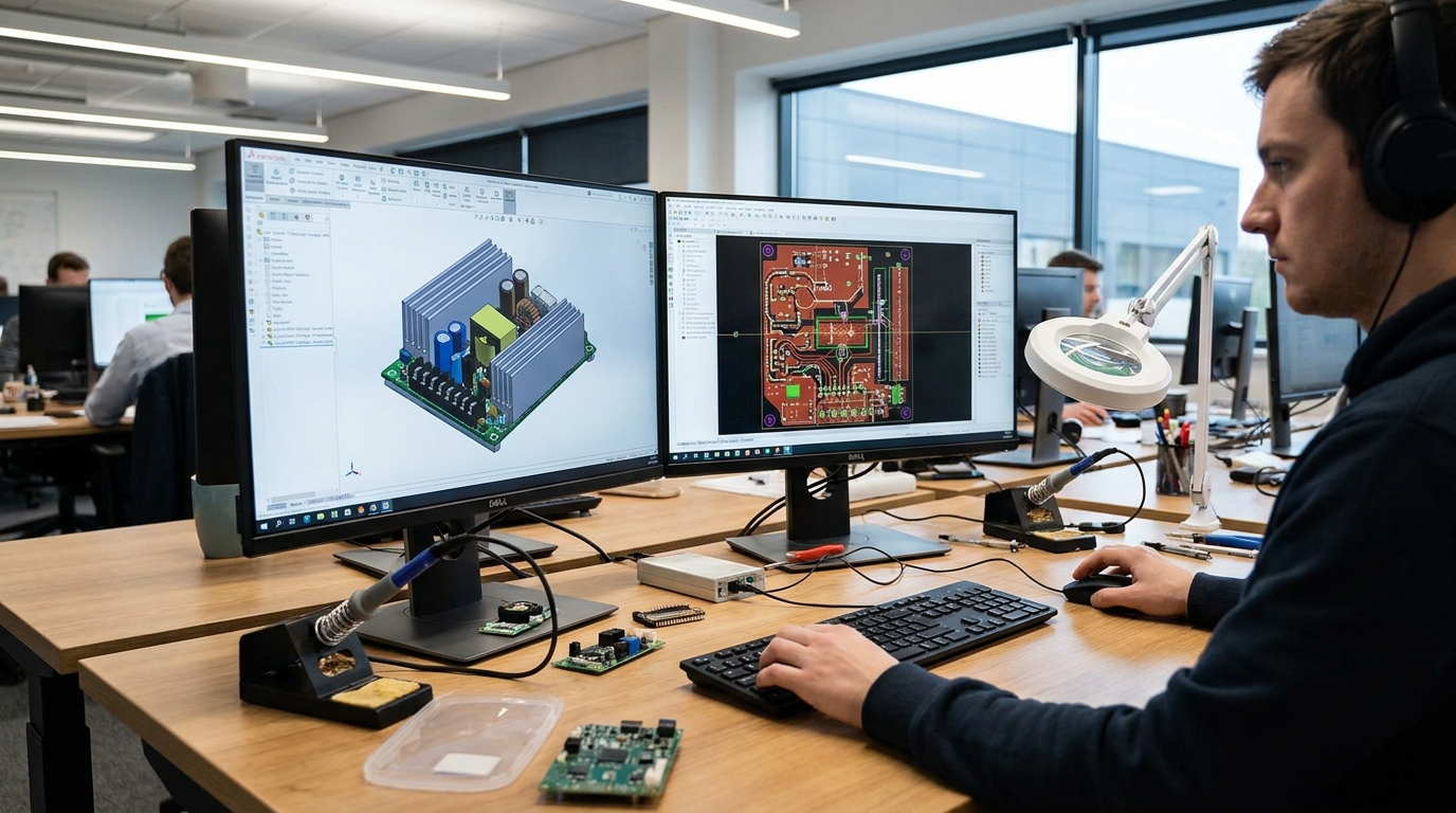
Manufacturers can optimize isolation voltage in power supplies by utilizing precise CAD routing layouts, cutting physical isolation slots in the PCB, and integrating premium triple-insulated transformer components. These advanced engineering techniques maximize safety performance without increasing the physical size of the power adapter housing. By carefully positioning the isolation barrier boundary across the board, designers ensure consistent isolation voltage in power supplies. This smart design process keeps your production costs highly competitive while delivering robust safety.
Physical routing is complemented by strict supplier audits to ensure that internal components like optocouplers and capacitors meet strict international requirements. By eliminating manufacturing defects and physical air gaps, builders achieve incredibly high dielectric resistance. Sourcing your adapters from a certified manufacturing partner ensures that these complex variables are managed professionally. Let us look at the key techniques that drive modern optimization.
What Layout Strategies Deliver Premium Performance?
Here is why: a smart PCB layout is the difference between a reliable product and a costly field recall. By routing high-voltage and low-voltage sections on opposite sides of the board, you naturally maximize physical safety gaps. This strategic design ensures your system easily passes strict agency testing protocols. It eliminates the risk of trace spacing being compromised during high-volume production runs.
- Isolation Slots: Physical air gaps routed into the circuit board to eliminate surface creepage tracking.
- Triple-Insulated Windings: Eliminates bulky tape layers to keep transformer designs compact and efficient.
- Guard Trace Shielding: Diverts capacitive leakage current safely to ground to prevent digital signal errors.
When you partner with an experienced manufacturer, you benefit from these optimized layout techniques right out of the box. This collaboration ensures your power adapter design is perfectly optimized for safety, cost, and long-term reliability. You can rely on expert engineering teams to solve your most complex physical layout challenges. It is the fastest path to launching a successful and safe commercial product.
Key Takeaway: Optimizing board layout geometries and internal component choices maximizes safety barriers without adding bulk to your device.
| Optimization Strategy | Production Complexity | Manufacturing Cost Impact | Core Safety & Reliability Benefit | |
|---|---|---|---|---|
| Routed Isolation Slots | Low to Moderate | Very Low | Significantly boosts surface tracking resistance | |
| Triple-Insulated Wire | Medium | Low to Moderate | Removes bulky transformer tape, shrinking form factor | |
| Premium Y-Capacitors | Low | Low | Assures safe fail-open protection during severe spikes |
These optimization methods show how smart design engineering delivers maximum safety while keeping manufacturing efficient.
Conclusion: Secure Your Power Supplies
Choosing high-performance power adapters with robust isolation barriers is the ultimate way to protect your business from expensive electrical faults and severe safety hazards. At MK Power Adapter, we design and manufacture globally certified, industrial-grade power solutions that solve your most challenging energy delivery and isolation problems. If you need custom OEM/ODM support or certified adapters for your next project, feel free to contact us to discuss your unique technical requirements. Our industry-leading manufacturing bases stand ready to deliver the high-quality, reliable power systems your modern infrastructure demands.
By prioritizing material quality and rigorous safety testing, we ensure that your systems remain completely operational under any grid conditions. Partnering with a dedicated power expert allows you to focus on scaling your business with complete peace of mind. Let us help you secure your hardware and optimize your power architectures with our premium, globally certified adapters. Secure your equipment today and elevate your operational safety standards with our high-reliability power solutions.
Frequently Asked Questions
Can I use a power supply with a lower isolation voltage than my application specifies?
No, you must never use an under-specified isolation barrier. Doing so risks catastrophic hardware destruction during minor power spikes, compromises operator safety, and instantly voids your device’s international safety certifications.
What’s the best way to determine the correct isolation rating for my product?
The best way is to identify the regulatory safety standards governing your target market. For example, medical systems require strict compliance with IEC 60601-1 (such as 2xMOPP), whereas standard IT and AV setups are governed by the hazard-based IEC 62368-1 standard.
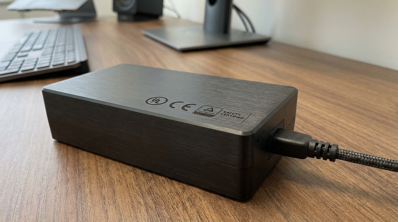
How do I know if my power adapter has successfully passed safety isolation testing?
You can confirm safety verification by inspecting the product’s casing for recognized certification markings. Look for logos from leading global safety testing agencies like UL, CE, TUV, and VDE. You can also request an official safety report directly from your manufacturing partner to confirm compliance.
Can extreme humidity permanently degrade my power supply’s insulation barrier?
Yes, continuous high humidity will permanently reduce the dielectric safety threshold of your power supply. Moisture combines with airborne dust particles to create conductive surface tracking paths that slowly bridge your isolation gaps.
Can I trust a standard consumer-grade power adapter for high-altitude industrial applications?
No, standard consumer power adapters are not engineered for the reduced air pressure of high altitudes. Thinner air ionizes much more easily, which can cause spark-over arcing unless the board was specifically designed with larger physical spacing gaps.