Understanding leakage current in power adapters requires a clear grasp of unintended electrical flows traveling through insulation barriers or grounding networks. By tracking how alternating current escapes through parasitic paths, design engineers can safely protect users from touch voltages. To achieve this, you must systematically isolate noise-filtering components from outer user interfaces.
Imagine preparing to launch a new consumer device, only to face delayed market entry because of touch voltage failures. This frustrating bottleneck is almost always triggered by unmanaged leakage current in power adapters bypassing primary safety barriers. To eliminate this issue and ensure safety, you must implement optimized electrical topologies. Working with a dedicated manufacturing partner helps you easily meet safety limits and protect your brand’s reputation.
What Is Leakage Current in Power Adapters?

Leakage current in power adapters represents the unintended flow of electrical current that passes through an insulation barrier, protective earth path, or enclosure to the surrounding environment instead of remaining in the closed functional loop. This stray current is primarily driven by capacitive coupling, parasitic capacitance in transformers, or microscopic insulation imperfections. Under normal operation, small amounts of current inevitably find alternative paths to ground.
Why does current flow outside its intended path?
Unintentional electrical paths are established when alternative high-frequency impedances exist alongside the main functional conductor. Parasitic capacitance forms between transformer windings and on the PCB ground planes, creating a path for high-frequency common-mode noise.
Think about it: this stray capacitance cannot be entirely eliminated due to the physical proximity of components.
- Parasitic Capacitance: Naturally occurs between primary and secondary transformer coils.
- EMC Filtering: Connects safety capacitors from AC lines to ground to filter noise.
- Dielectric Limitations: Real-world insulators possess finite resistance and non-zero admittance.
Is a small amount of leakage inevitable?
All high-frequency switching mode power supplies (SMPS) will exhibit some level of touch current during normal operation. The active switching of semiconductors generates high dV/dt nodes that naturally couple to any nearby grounded conductors.
Here is the catch: removing filter components entirely to stop leakage will cause the adapter to fail global EMI tests.
- Switching Frequencies: High dV/dt transitions generate high-frequency AC stray paths.
- Component Proximity: Compact layouts increase capacitive coupling to the chassis.
- Safety Trade-offs: Noise suppression methods directly contribute to small leakage pathways.
Key Takeaway: Unintended leakage current is an inevitable byproduct of electromagnetic compatibility filtering and high-frequency switching, requiring careful physical layout management to keep currents below touch safety thresholds.
| Source Type | Physical Mechanism | Current Type | Typical Current Range | |
|---|---|---|---|---|
| Y-Capacitors | Direct shunt to ground/neutral | AC (mains frequency) | 50 µA to 1.5 mA | |
| Transformers | Parasitic inter-winding coupling | AC (high frequency) | 5 µA to 50 µA | |
| Semiconductor Frames | Frame-to-heatsink capacitance | High-frequency AC | 2 µA to 20 µA |
Analyzing the primary sources reveals that capacitive elements dominate the stray electrical paths, demanding highly optimized physical layouts.
Why Does Leakage Current in Power Adapters Occur?

Unintended leakage current in power adapters occurs due to the fundamental physics of switching-mode topologies, where high-speed semiconductor transitions interact with parasitic capacitive paths. Additionally, safety filters designed to suppress electromagnetic noise provide a direct channel for currents to escape to earth. Understanding these coupling paths is essential for optimizing system isolation.
What role do parasitic capacitances play?
High-frequency switching elements create rapid voltage transitions that force alternating current through very small parasitic capacitance paths. These paths exist inside the switching transformer, under the PCB copper planes, and between transistor cases and heatsinks.
But wait, there is more: even minor spacing reductions in high-density layouts can significantly inflate these currents.
- Inter-winding Capacitance: Coupling of high dV/dt from primary to secondary transformer coils.
- PCB Parasitics: Copper traces running close to grounded planes create stray capacitors.
- Heatsink Coupling: Insulated semiconductors mounted on metal frames create a bypass route.
How do safety components increase leakage?
Safety components like safety capacitors are deliberately placed across the isolation barrier to shunt electromagnetic noise. However, these capacitors form a direct path for mains frequency currents to flow into the output ground or protective earth.
Think about it: you are essentially trading electrical quietness for a small leakage pathway.
- Class-Y Capacitors: Connect primary line/neutral to earth or secondary ground.
- Input Filter Networks: AC lines bypassed to ground to block incoming mains transients.
- Varistors: Transient voltage surge suppressors can introduce tiny leakage paths as they age.
Key Takeaway: The physical necessity of EMI filtering coupled with structural parasitic capacitances creates inevitable leakage paths that you must minimize through advanced transformer winding techniques.
| Factor | Root Cause | Safety / EMI Impact | Engineering Solution | |
|---|---|---|---|---|
| Transformer Parasitics | Inter-winding coupling | High-frequency noise output | Insert internal Faraday shield | |
| Filter Capacitance | Class-Y noise shunting | Elevated mains leakage current | Optimize capacitance values | |
| PCB Layout | Close trace proximity | Parasitic trace leakage | Maximize creepage distances |
Understanding these mechanical and electrical factors allows design engineers to implement targeted shielding to intercept stray currents before they cross the isolation barrier.
How Does Leakage Current in Power Adapters Affect User Safety?
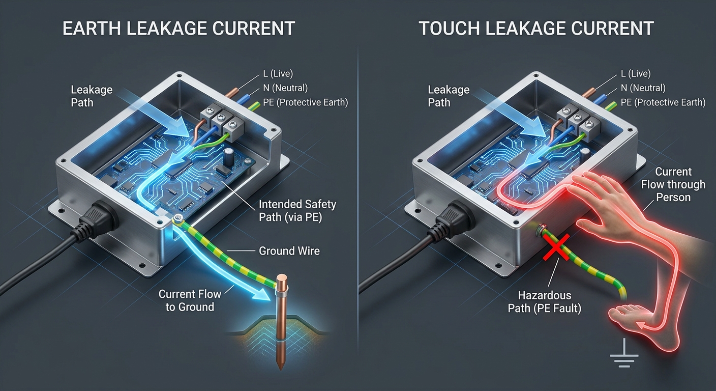
Excessive leakage current in power adapters affects user safety by posing a direct risk of electric shock, which can range from a mild tingling sensation to severe cardiac disruption. Under single-fault conditions, such as a broken ground wire, this stray current will use the human body as the path of least resistance to earth. Therefore, designers must restrict touch currents to highly safe levels.
What happens during an earth fault?
If the protective grounding wire fails or is disconnected, the touch current accumulates on the metallic chassis or exposed conductive parts. When a user touches the outer frame, the entire leakage current travels through their body to ground.
Here is the catch: without an active ground path, even standard equipment can become a safety hazard.
- Broken Protective Earth: Eliminates the low-impedance route meant to carry fault currents safely.
- Touch Voltage: Builds up on the chassis, presenting a shock hazard to the operator.
- Tissue Current Path: Current flows through skin and vital organs to find a physical path to ground.
Can microshocks be hazardous?
Even currents below the human perception threshold of one milliamp can be dangerous in specialized environments. For patients in hospitals with open internal pathways, micro-amperes of current can trigger ventricular fibrillation.
Think about it: what is a minor tingle to a healthy operator can be fatal in clinical scenarios.
- Intact Skin Resistance: Typically protects healthy operators from currents under one milliamp.
- Direct Internal Paths: Bypass the outer skin barrier, directing currents straight to the heart.
- Involuntary Reactions: Can cause startle responses that lead to physical accidents in workspaces.
Key Takeaway: Leakage current poses different safety risks depending on user environment and physiological state, making robust grounding and fail-safe insulation critical.
| Current Level | Safe for Healthy Operators? | Safe for ICU Patients? | Typical Physiological Effect | |
|---|---|---|---|---|
| < 10 µA | Yes | Yes | Undetectable by human nervous tissues | |
| 100 µA | Yes | No | Threshold of perception on internal tissues | |
| 1.0 mA | Yes (Slight tingle) | No | Mild electric shock, involuntary reaction | |
| > 10 mA | No | No | “Can’t let go” threshold, muscle spasms |
These strict physiological limits highlight why medical safety certifications require significantly lower leakage currents than standard commercial standards.
What Are the Acceptable Limits for Leakage Current in Power Adapters?
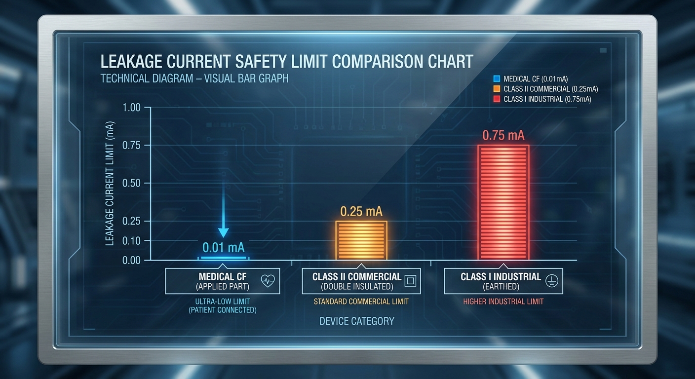
Acceptable limits for leakage current in power adapters are strictly defined by international safety standards, ranging from a tight 10 µA limit for medical cardiac devices to 3.5 mA for industrial equipment. These regulatory boundaries ensure that normal leakage never exceeds the physiological safety threshold of users. Design engineers must strictly respect these safety limits during the development phase.
What are the commercial limits?
Standard commercial and information technology (IT) equipment operates under relaxed limits because operators are assumed to be healthy with dry, intact skin. For Class I grounded devices, a baseline limit of 3.5 milliamperes is globally accepted.
But wait, there is more: Class II double-insulated devices operate under much tighter constraints since they lack safety grounds.
- Class I Grounded: Allowed up to 3.5 mA under typical working conditions.
- Class II Double-Insulated: Strictly limited to 0.25 mA due to lack of earth ground.
- Handheld Commercial: Kept below 0.75 mA to prevent strong shock reactions.
Why are medical limits so low?
Medical limits are ultra-low to prevent microshock hazards in patients who may be sedated, weak, or physically connected to cardiac devices. The standard restricts normal touch current to 100 µA and patient leakage to 10 µA for cardiac devices.
Think about it: a patient’s physiological defense system is highly compromised under clinical care.
- Type CF Cardiac: Enforces a strict 10 µA limit under normal operating conditions.
- Type BF Body Floating: Allows up to 100 µA for general medical skin contact.
- Single Fault Limits: Ensures safety even with a disconnected ground, capped at 500 µA.
Key Takeaway: Navigating safety limits requires you to match the adapter’s safety class with the specific vulnerability of the end-user environment.
| Standard | Application | Earth Leakage NC | Touch Current NC | |
|---|---|---|---|---|
| IEC 62368-1 | IT & Audio/Video | Up to 3.5 mA | 0.25 mA (Class II) | |
| IEC 60601-1 BF | Medical (Skin Contact) | 500 µA | 100 µA | |
| IEC 60601-1 CF | Medical (Cardiac Contact) | 500 µA | 10 µA (Patient Leakage) |
Selecting an adapter with the appropriate certification class guarantees that your product meets international compliance standards.
How Is Leakage Current in Power Adapters Measured?
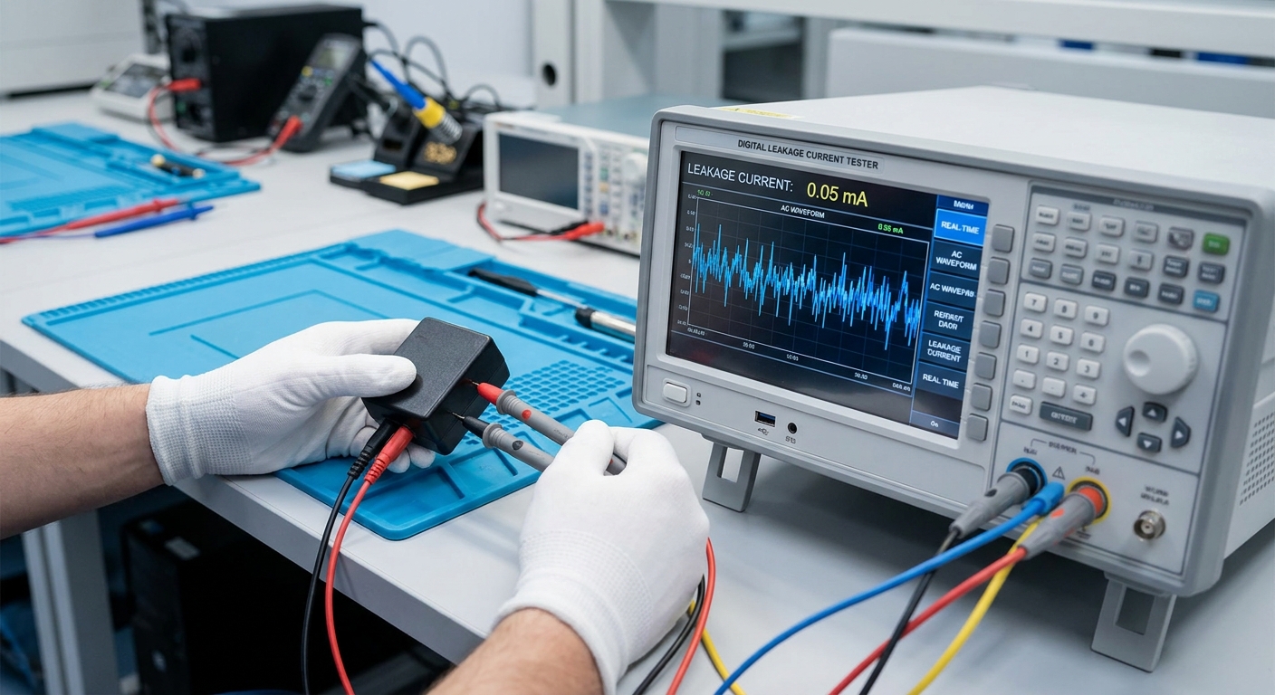
To measure leakage current in power adapters accurately, you must use a specialized compliance analyzer equipped with an RC network that simulates human skin impedance. Standard handheld multimeters are insufficient because they lack the high-frequency measurement bandwidth and fail to emulate real-world human tissue impedance. This ensures your measurements align with actual human safety parameters.
How does the simulated human body work?
Safety testing protocols require a standard RC network, typically a 1 kΩ resistor in parallel with a small capacitor, to mimic the human body’s impedance. The voltmeter measures the voltage drop across this network, allowing the analyzer to calculate the true leakage current.
Here is the absolute best part: this test simulates the actual resistive and capacitive path of a human touching the device.
- Tissue Emulation: Uses a 1,000-ohm resistor to model internal body fluid resistance.
- Skin Capacitance: Integrates a parallel capacitor to simulate skin contact properties.
- High Frequency Roll-off: Filters out harmless, very high-frequency currents to align with human sensitivity.
What test conditions are required?
Testing must occur at 110% of the maximum rated input voltage to capture worst-case leakage values under normal and single-fault states. The testing process also involves reversing the line and neutral connections to locate any asymmetric leakage paths.
Think about it: safety must be maintained even under extreme mains instability and reverse-wiring scenarios.
- Over-Voltage Testing: Operating the unit at 264VAC for a nominal 240VAC rating.
- Single-Fault Simulation: Testing safety limits with open-earth or open-neutral lines.
- Polarity Reversal: Flipping live and neutral wires to identify structural capacitive imbalances.
Key Takeaway: Accurately measuring leakage requires high-precision equipment that simulates the human nervous system’s response to high-frequency currents.
| Measurement Method | Equipment Required | Compliance Level | Primary Use Case | |
|---|---|---|---|---|
| RC Circuit Probe | Voltmeter + 1kΩ / 0.15µF Network | High | Initial engineering bench validation | |
| Differential Current | Sensitive Clamp Meter | Medium | Quick manufacturing-line verification | |
| Dedicated Safety Tester | Automated Safety Analyzer | Maximum | Formal laboratory certification testing |
Implementing these rigorous laboratory tests guarantees that your product’s power adapter design is safe for the consumer market.
Which Standards Regulate Leakage Current in Power Adapters?
Global standards regulating leakage current in power adapters include IEC 60601-1 for medical systems, IEC 62368-1 for IT and audio-visual consumer devices, and IEC 60335-1 for household appliances. These standards lay down exact structural guidelines, including isolation distances, to protect different groups of end-users. Selecting the appropriate standard is the first step toward market compliance.
How does IEC 62368-1 differ?
IEC 62368-1 replaces older standards with a hazard-based safety approach, classifying electrical energy sources into three distinct hazard tiers. It focuses on the energy transferred to the skin, allowing up to 2.0 mA for standard desktop applications.
Let’s get right to the point: this standard assesses the transfer of energy rather than setting rigid construction requirements.
- Energy Tiers: Classifies voltages and currents into ES1, ES2, and ES3 energy classes.
- Operator Focus: Prioritizes protection for healthy users touching standard metallic enclosures.
- Failsafe Protections: Demands double or reinforced insulation barriers if grounding paths fail.
What makes IEC 60601-1 unique?
IEC 60601-1 focuses strictly on patient safety, requiring very low touch and auxiliary currents to prevent harm to vulnerable hospital patients. It enforces strict rules on isolation, dielectric barriers, and component clearances to guarantee patient protection.
Think about it: patients may be unable to physically move or respond to electrical hazards during medical procedures.
- Patient Context: Assumes patients cannot pull away from electric shocks during treatment.
- MOPP vs. MOOP: Differentiates between patient-protection (MOPP) and operator-protection (MOOP) methods.
- Critical Fault Audits: Enforces safety verification under complex single-fault conditions.
Key Takeaway: You must choose a power adapter certified under the specific standard matching your product’s application to prevent compliance delays.
| Standard | Core Target Audience | Ground Condition | Enclosure Limit NC | |
|---|---|---|---|---|
| IEC 62368-1 | General Consumers & ITE | Class I | 0.25 mA (Class II) / 3.5 mA (Class I) | |
| IEC 60601-1 BF | Hospital Patients (Skin Contact) | Class I / Class II | 100 µA | |
| IEC 60601-1 CF | ICU Patients (Cardiac Contact) | Class I / Class II | 10 µA (Patient Leakage) |
Aligning your system development with these regulations from day one ensures a smooth path through certification labs.
How Do Y Capacitors Influence Leakage Current in Power Adapters?
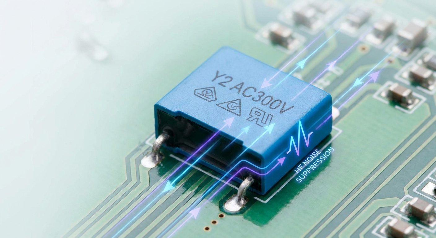
Y capacitors influence leakage current in power adapters by serving as the primary physical route for AC mains current to bypass the isolation barrier and escape to ground. Although these specialized safety components are essential for bypassing common-mode EMI noise, their capacitance directly increases leakage current. Managing this capacitive leakage pathway is a core focus of modern high-frequency design.
Why are Y capacitors necessary for EMI?
Without Y safety capacitors, high-frequency common-mode noise would propagate onto the DC output cables, turning them into radiating antennas that fail EMI standards. These capacitors shunt high-frequency noise back to the primary side.
Here is the catch: reducing noise radiation through these shunts naturally opens up a leakage path for mains frequency current.
- Common-Mode Filtering: Provides a low-impedance path for high-frequency common-mode emissions.
- Antenna Suppression: Blocks AC cord noise from radiating out of the output cables.
- Safety Isolation: Specially designed to fail open-circuit to prevent electric shock hazards.
How do we balance EMI and safety?
Engineers face a direct trade-off: larger Y capacitor values lower common-mode noise but increase mains-frequency leakage current. Minimizing Y capacitor values requires you to invest in bulkier and more complex common-mode chokes on the input stage.
Think about it: you are swapping passive capacitive shunts for active or inductive filtering to keep touch current low.
- Capacitance Budgeting: Limiting Class-Y values to under 470 pF for low-leakage layouts.
- Inductive Compensation: Utilizing larger common-mode inductors to maintain noise suppression.
- PCB Shield Optimization: Adding internal ground planes to redirect noise without using capacitors.
Key Takeaway: Optimizing Y-capacitance is a delicate balancing act that requires you to trade capacitive shunts for high-performance inductive filtering.
| Y-Capacitance Value | EMI Suppression Level | Measured AC Leakage Current | Target Compliance Standard | |
|---|---|---|---|---|
| None | Extremely Poor (Fails) | < 5 µA | None (Non-compliant) | |
| 100 pF | Low | ~15 µA | IEC 60601-1 CF (Medical) | |
| 470 pF | Moderate | ~70 µA | IEC 60601-1 BF (Medical) | |
| 2200 pF (2.2 nF) | High | ~330 µA | IEC 62368-1 (IT Equipment) |
This technical trade-off shows why low-leakage power adapters require advanced, highly optimized EMI input stage designs.
Is Ground Leakage Different from Leakage Current in Power Adapters?
Ground leakage is a specific sub-category of leakage current in power adapters that flows exclusively through the protective earth conductor, whereas other types like touch current flow through exposed enclosures when touched by a user. Understanding this distinction is key to choosing the right power design for grounded Class I or ungrounded Class II systems. Both currents must be modeled during structural analysis.
What is the path of earth leakage?
Earth leakage current flows directly from internal components through the protective ground wire of a Class I power supply into the electrical panel. This current is safe during normal operation because the grounding wire provides a low-impedance return path.
But wait, there is more: if that dedicated copper return path breaks, the earth leakage current instantly becomes dangerous touch current.
- Protective Earth Wire: Safely returns currents to earth ground, bypassing the user.
- Class I Design Requirement: Demands a continuous 3-wire AC path with dedicated earth.
- Asymptotic Shielding: Relies on copper transformer shields connected to the primary earth.
How does touch current differ?
Touch current refers to the current that flows through a person touching the plastic enclosure of an ungrounded Class II adapter. Because Class II devices lack a ground pin, safety rests on the plastic enclosure’s insulation properties.
Think about it: a Class II device depends entirely on structural isolation layers rather than external physical wiring.
- Class II Ungrounded: Uses a 2-wire AC cord and relies on reinforced insulation.
- Chassis Touch Path: Measures leakage through a metal foil wrapped around the plastic case.
- Critical Fault Focus: Relies on isolation layers to prevent current from reaching the chassis.
Key Takeaway: Earth leakage relies on a functional grounding path for safety, whereas touch current must be structurally limited to protect users from broken grounds.
| Parameter | Earth Leakage Current | Touch Current | |
|---|---|---|---|
| Primary Flow Path | Dedicated ground wire | Human body to earth ground | |
| Appliance Safety Class | Class I (Earthed) | Class I and Class II (Double-Insulated) | |
| Worst-Case Fault Mode | Broken/disconnected wall ground | Insulation barrier puncture | |
| Typical NC Limits | 500 µA (Medical) / 3.5 mA (IT) | 100 µA (Medical) / 250 µA (IT) |
This technical distinction shows why you must analyze both ground paths and surface touch barriers during the safety verification phase.
How Can Manufacturers Reduce Leakage Current in Power Adapters?

Manufacturers can reduce leakage current in power adapters by using multi-layer transformer shielding to capture common-mode current internally and by substituting large Y capacitors with higher-inductance common-mode chokes. These active design measures lower leakage currents without sacrificing electromagnetic compatibility. Implementing these measures requires specialized knowledge of high-frequency power electronics.
How does transformer shielding work?
Placing a grounded physical copper shield between the primary and secondary transformer windings diverts capacitive currents back to primary ground before they can cross the isolation barrier. This approach drops inter-winding parasitic capacitance by up to 80%.
Here is the secret weapon: by intercepting these capacitive currents early, you avoid relying heavily on noisy bypass capacitors.
- Faraday Shielding: Electrostatic copper foil intercepts high-frequency electric fields.
- Primary Ground Return: Returns stray currents safely to input ground without crossing barriers.
- Minimal Impedance Impact: Maintains tight magnetic coupling while reducing parasitic paths.
Can layout optimization assist?
Careful PCB design that isolates high dV/dt copper nodes from grounded chassis planes significantly reduces parasitic capacitance. Increasing spacing between primary and secondary circuits minimizes stray surface paths.
Think about it: a clean, spacious board layout naturally acts as an insulator, reducing parasitic coupling without adding component costs.
- Trace Separations: Maintaining wide distances on switching nodes to prevent layout coupling.
- Creepage and Clearance: Exceeding safety clearances to prevent humidity-induced current tracking.
- Conformal Coating: Applying safety coatings to seal PCBs from dust and moisture.
Key Takeaway: Reducing leakage requires a dual-pronged approach: shielding internal transformer capacitive paths and optimizing trace geometries on the PCB layout.
| Engineering Solution | Technical Mechanism | Touch Leakage Reduction | EMI Filtration Impact | |
|---|---|---|---|---|
| Inter-layer Faraday Shield | Intercepts stray transformer currents | Up to 80% reduction | Neutral | |
| Split Inductive Chokes | Increases input filter impedance | Up to 50% reduction | Highly Positive | |
| Trace Spacing Enlargement | Lowers parasitic board capacitance | Up to 30% reduction | Neutral |
Integrating these high-end layout methodologies allows manufacturers to build ultra-safe, low-leakage power adapters that excel in compliance testing.
Why Is Leakage Current in Power Adapters Critical for Med/Ind?
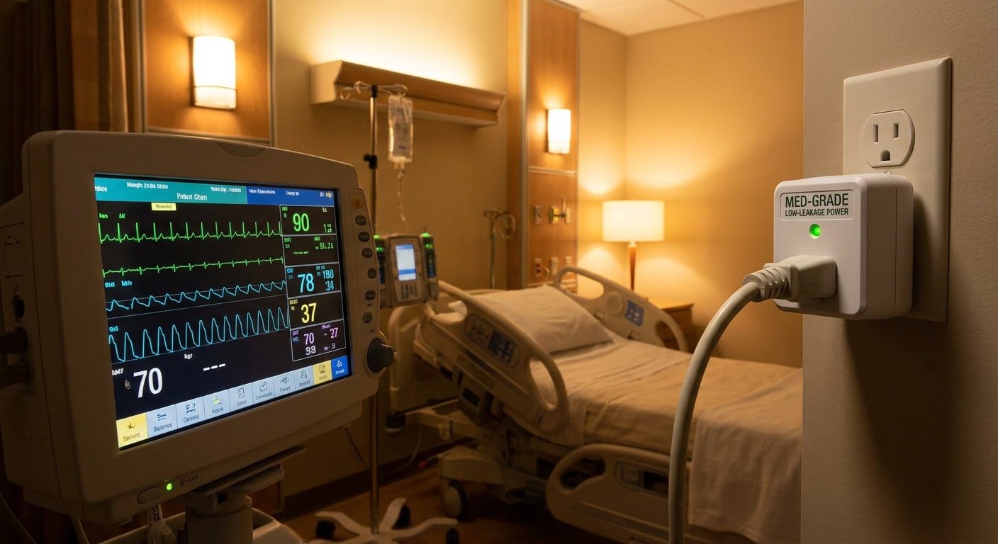
Managing leakage current in power adapters is critical for medical and industrial applications because excessive stray currents can interfere with sensitive clinical sensors or cause electric shock in patients with direct internal pathways. In industrial environments, unmanaged leakage currents can cause false ground fault alarms or degrade high-speed automated systems. Ensuring safe electrical isolation is paramount in these specialized fields.
Why are clinical settings so sensitive?
Patient monitoring devices use high-gain amplifiers that are easily disrupted by tiny AC leakage currents. If an adapter leaks current, it can introduce 50/60Hz noise into patient monitoring lines, corrupting vital diagnostic data.
Here is the absolute best part: by using medical-grade power adapters, you isolate patients from these sensitive signal disruptions.
- Sensor Interference: High-impedance sensors are sensitive to stray electrostatic noise.
- Signal Distortion: Noise on ECG monitors can mimic or obscure heart rhythm abnormalities.
- Isolation Integrity: Direct patient contact demands double-insulated, low-leakage power inputs.
What are the industrial risks?
Modern automated factories connect hundreds of devices to a shared safety grounding network. If individual power adapters exhibit moderate leakage, the cumulative current can trip ground fault circuit interrupters (GFCIs), causing expensive factory shutdowns.
Think about it: a single poorly designed power supply can introduce enough noise to shut down an entire manufacturing line.
- Cumulative Leakage: Multiplied leakage over dozens of parallel devices trips GFCIs.
- Control Interference: High-frequency stray current degrades low-voltage PLC signals.
- System Downtime: Unplanned line shutdowns caused by ground loop noise issues.
Conclusion
Managing leakage current in switching power systems requires a careful balance between safety and electromagnetic interference compliance. Whether you are designing clinical devices or industrial automation platforms, selecting low-leakage power systems is essential for user safety and system stability. By partnering with a specialized B2B manufacturer, you can bypass design risks and easily secure safety compliance. If you need custom power adapters that combine low leakage currents with global certifications, contact us to work directly with our engineering team. We are committed to powering global B2B innovation with clean, safe, and highly reliable energy conversion solutions.
FAQ
Can I use an IT-grade power adapter for medical device design?
No, you cannot safely do this. Power adapters certified under IT standards (IEC 62368-1) can leak up to 3.5 mA of current. This far exceeds the 100 µA touch limit and 10 µA patient limit required for clinical applications under IEC 60601-1, creating dangerous shock hazards.
What’s the best way to reduce adapter leakage current without failing EMI tests?
The best method is to reduce Y capacitor values and compensate with higher-inductance common-mode chokes. Additionally, inserting an electrostatic Faraday shield between the primary and secondary transformer windings helps divert capacitive currents back to primary ground before they can cross the isolation boundary.
How do I know if my power adapter’s leakage current is safe?
You must measure the touch current using a dedicated tester configured with a human body RC simulation network. Standard handheld multimeters cannot capture the high-frequency components of switching leakage. If the touch leakage is under 0.25 mA for Class II devices or under 100 µA for medical environments, the adapter is safe.
Can I connect multiple power adapters to a single grounded bus without increasing leakage?
No, you cannot prevent leakage current accumulation. In parallel power configurations, individual adapter leakage currents add up along the shared grounding network. If cumulative leakage exceeds threshold limits, it can trip ground fault circuit interrupters (GFCIs) and introduce electrical noise.
What’s the best component selection criteria for high-reliability Class-Y safety capacitors?
You should always select safety-certified Class Y1 or Y2 capacitors from reputable manufacturers. Quality safety capacitors are designed with self-healing dielectrics that are guaranteed to fail open-circuit under high-voltage transients, preventing direct insulation puncture and electric shock hazards over years of service.