Power adapters overheat primarily due to internal electrical resistance, excessive current draw, or inefficient heat dissipation during the voltage conversion process. Imagine your enterprise deployment running critical IT, networking, or medical hardware, when suddenly a system goes offline. You run a physical inspection and find a hot, failing block of plastic, disrupting your operations and threatening downstream systems with instability, structural damage, or severe fire hazards. Addressing issues related to power adapter overheating early in the product lifecycle is vital to maintaining medical-grade reliability and regulatory compliance. Gaining a deep understanding of thermal management and preventive actions is the key to securing hardware uptime and preventing these vulnerabilities.
What Causes Power Adapter Overheating?
Power adapters overheat due to a combination of inherent electrical conversion losses, environmental heat stacking, and excessive current demands from the connected payload. This thermal rise occurs as the adapter converts high-voltage alternating current (AC) into low-voltage direct current (DC), dissipating excess energy as heat. If this heat is not managed properly, you will experience power adapter overheating that risks shutting down your active operations. Mitigating this risk requires analyzing the physical limits of your power supply architecture.
Every electronic power converter operates under the laws of thermodynamics, where no energy transfer is completely efficient. The lost electrical energy is converted into heat, concentrated mainly in the switching transistors, rectifier diodes, and copper transformer windings. If the component layout cannot shed this thermal energy fast enough, the internal operating temperature will climb steadily. Understanding these thermodynamic realities allows you to anticipate failures before they compromise your systems.
Why Does Energy Conversion Generate Excess Heat?
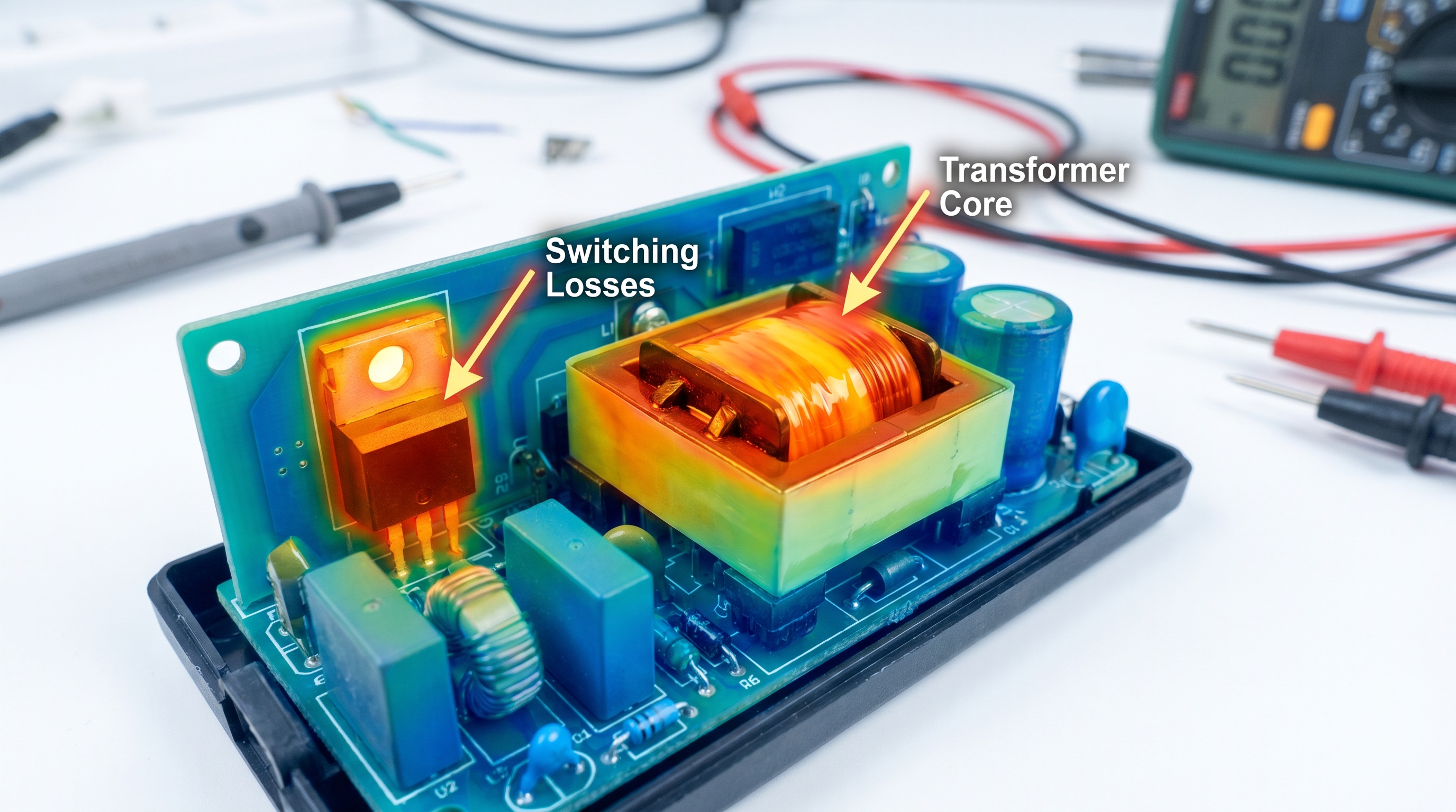
The primary driver of heat during the power conversion process lies in the high-frequency switching operations of internal semiconductors. As power MOSFETs cycle on and off thousands of times per second, they experience transient resistance states that generate constant switching losses. But here is the kicker: as ambient temperatures rise, this resistance increases, creating a feedback loop that amplifies heat generation. To map these dynamics, engineers isolate the specific components where energy dissipation is highest.
- Switching Losses: Occur during the high-frequency transitions of primary-side MOSFETs.
- Conduction Losses: Generated by current passing through the internal resistance of copper windings and silicon junctions.
- Magnetic Losses: Dissipated within the transformer core as eddy currents and hysteresis losses.
Key Takeaway: Identifying where thermal dissipation occurs helps you evaluate power supplies with sufficient thermal margins. By choosing adapters with optimized switching profiles and low-resistance copper traces, you can prevent thermal failure modes from interrupting your field equipment.
| Thermal Source Component | Primary Loss Mechanism | Key Heat Dissipation Method | Critical Risk Threshold | |
|---|---|---|---|---|
| Switching MOSFETs | High-frequency transition resistance | Attaching copper or aluminum heatsinks | >125∘C junction temp | |
| Transformer Core | Core hysteresis and eddy currents | Air gap convection and wire insulation | >110∘C core temp | |
| Rectifier Diodes | Forward voltage drop under heavy currents | Copper PCB plane thermal vias | >150∘C junction temp |
The data above highlights how specific components generate unique thermal footprints during standard energy conversion cycles.
Why Does Power Adapter Overheating Damage Electronic Devices?
Power adapter overheating damages electronic devices by compromising the voltage regulation feedback loop, which leads to unregulated voltage spikes or severe power ripples passing directly into sensitive downstream circuits. When high thermal loads degrade internal components like optocouplers, the adapter loses its ability to tightly regulate its output. If this regulation fails, the resulting power adapter overheating can deliver destructive over-voltage conditions to your expensive enterprise hardware. This voltage instability can instantly burn out microprocessors or cause system-wide logic errors.
Additionally, excessive heat from the power supply can travel down the copper conductors of the DC delivery cable, increasing the thermal stress on the receiving device’s input connector. This localized heat transfer accelerates the wear on the device’s internal charging circuits and battery management systems. Over time, these thermal stresses lead to micro-fractures in solder joints and physical warping of the device substrate. Protecting your high-value equipment requires recognizing how power supply health dictates overall system reliability.
Can Overheated Adapters Degrade Downline Regulators?
Downstream DC-to-DC converters are designed to receive clean, stable input voltages, but a thermally stressed power adapter disrupts this balance. When the power supply’s output filters degrade under heat, high-frequency voltage ripples bypass the filters and overload the device’s internal regulators. Let’s face it: your downline hardware was not engineered to filter out massive voltage fluctuations caused by a failing adapter. This thermal stress eventually breaks down the protective semiconductor barriers within your device’s motherboard.
- Voltage Regulation Breakdown: The failure of feedback loops causes output voltage to spike beyond safe device limits.
- High Output Ripple: Degraded capacitors allow high-frequency AC noise to reach downline digital circuits.
- Connector Stress: Conductive heat traveling down the cable raises the operating temperature of input ports.
Key Takeaway: Understanding how power supply failures propagate downstream helps you protect high-value hardware deployments from expensive, premature replacement cycles. By selecting power adapters with built-in over-voltage protection (OVP) and low output ripple, you shield your systems from the destructive consequences of voltage runaway.
| Device Component at Risk | Failure Mechanism | Operational Symptom | Primary Mitigation Strategy | |
|---|---|---|---|---|
| Device Input Buck Regulator | Transistor breakdown from voltage spikes | Device fails to turn on / short circuit | Implement secondary Over-Voltage Protection | |
| Microprocessor Core | Noise interference from voltage ripple | Frequent system freezes or reboots | Use low-ESR solid polymer output capacitors | |
| Solder Joints / USB Ports | Micro-fractures from conductive heat | Intermittent charging or data link loss | Specify thermal-isolated power connector jacks |
The analysis above illustrates the direct relationship between power supply thermal degradation and downline component damage.
How Does Overloading Lead to Power Adapter Overheating?
Overloading leads to power adapter overheating because drawing more current than the adapter’s rated capacity exponentially increases the internal power dissipation through conduction losses. When a connected system draws excessive current, the heat generated within the adapter’s copper traces and semiconductor junctions rises as the square of the current (
P=I2R
). This rapid thermal accumulation quickly overwhelms the passive cooling capabilities of the adapter’s enclosure. If left unmanaged, this condition triggers power adapter overheating that degrades internal circuit boards.
Many systems suffer from overloading when users connect multiple peripherals or run high-power processing cycles that exceed the supply’s rating. While modern power adapters often feature over-current protection, prolonged operation near the absolute current limit still generates substantial heat. This thermal soak eventually dries out electrolytic capacitors and compromises the integrity of structural plastics. Managing this risk requires maintaining a healthy power headroom across all your device deployments.
Why Does Current Draw Increase Conduction Losses?
The relationship between current draw and heat generation is non-linear, meaning small increases in current yield massive jumps in thermal output. Every wire, connector, and circuit board trace has a small amount of internal electrical resistance that opposes the flow of electrons. Think about it: when you demand maximum performance, you are forcing more electrons through these narrow pathways, creating friction-like thermal energy. This continuous stress degrades the conductive efficiency of the copper traces, raising resistance and heat even further.
- Exponential Heat Growth: Conduction losses scale quadratically with current, making overloaded adapters heat up incredibly fast.
- Diode Voltage Drop: Rectifier diodes experience higher forward voltage drops under heavy current, releasing more heat.
- Copper Resistance Rise: As copper traces heat up, their electrical resistance increases, compounding thermal generation.
Key Takeaway: Standardizing on power adapters with a
20%
to
30%
power headroom (de-rating factor) protects your infrastructure from unexpected load spikes. This power reserve keeps the adapter operating within its high-efficiency sweet spot, reducing overall heat generation and extending component life.
| Load Level (% of Rating) | Relative Heat Generation | Primary Impacted Area | Expected MTBF Reduction | |
|---|---|---|---|---|
| 50% to 70% (Optimal) | Baseline | Balanced convective dissipation | 0% (Operates as designed) | |
| 85% to 100% (High Load) | 1.5x increase | Switching transistor thermal vias | Up to 30% lifespan reduction | |
| >110% (Overloaded State) | >2.5x exponential increase | Transformer windings and diodes | Immediate thermal protection cutoff |
The figures above outline how current loading directly dictates the thermal and mechanical lifespans of power adapters.
Can Poor Ventilation Increase Power Adapter Overheating Risks?
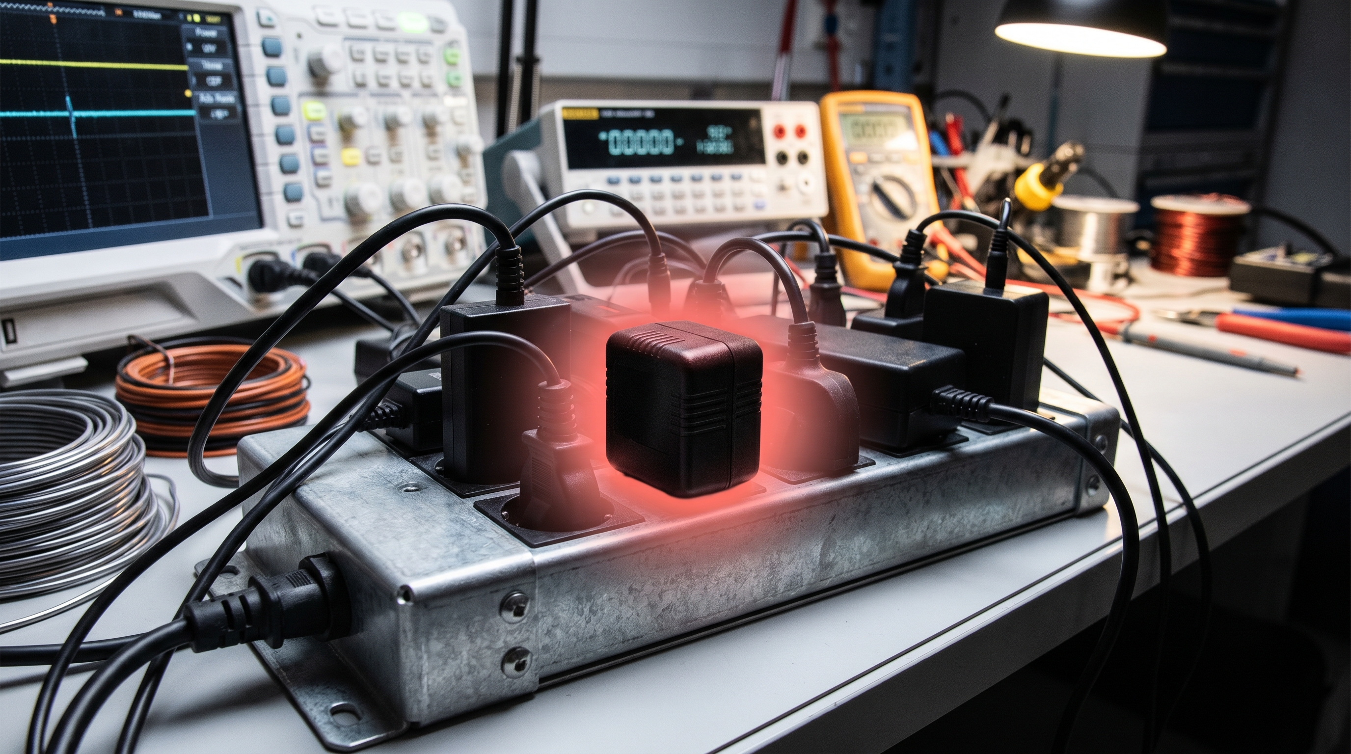
Poor ventilation significantly increases power adapter overheating risks by trapping convective heat within or immediately around the adapter’s sealed plastic enclosure. Since most wall-mount or desktop power adapters do not contain active cooling fans, they rely entirely on natural air convection to dissipate internal heat. When you place these adapters in enclosed spaces or cover them with debris, the surrounding boundary layer of air remains stagnant and rapidly absorbs heat. This localized thermal trapping is a primary driver of power adapter overheating in modern workplace installations.
In industrial settings or crowded server racks, multiple power supplies are often packed tightly together, creating a localized heat island. This concentration of thermal energy limits the adapter’s ability to transfer heat to the environment, even if the room is air-conditioned. Over time, this lack of airflow raises internal component temperatures beyond their maximum thermal thresholds. Proper ventilation planning is essential to ensure these units operate within their safe design limits.
How Does Trapped Airflow Accelerate Thermal Runaway?
When convective heat transfer is blocked, the temperature of the air immediately surrounding the adapter shell approaches the temperature of the internal components. This narrow thermal gradient slows down the rate of heat dissipation, forcing the internal components to operate at elevated temperatures. Let’s face it: without constant fresh airflow, even the most efficient power supplies will suffer from heat stacking. This accumulated thermal energy eventually degrades the protective insulation on transformer windings.
- Stagnant Boundary Layers: Lack of airflow prevents the natural convective removal of heat from the adapter’s plastic case.
- Localized Thermal Islands: Densely packed adapters transfer heat to one another, compounding overall thermal stress.
- Dust Accumulation: Particulate layers act as thermal insulation blankets, trapping heat directly inside the enclosure.
Key Takeaway: Implementing physical separation and maintaining minimum clearances around power adapters prevents localized heat pockets from forming. Ensuring that adapters are mounted on vertical surfaces with unimpeded convective paths preserves their thermal margins and shields your systems from premature shutdowns.
| Enclosure Environment | Ambient Temp Rise (ΔT) | Convective Cooling Efficiency | Recommended Action | |
|---|---|---|---|---|
| Open-Air Desktop | +10∘C to +15∘C | High (100%) | Standard passive clearance (50mm) | |
| Closed Server Cabinet | +25∘C to +35∘C | Medium (50%) | Integrate active exhaust cabinet fans | |
| Sealed Wall Cavity | +40∘C to +55∘C | Very Low (15%) | Use external DIN-rail power configurations |
The findings above demonstrate how physical spacing and ventilation patterns influence the operating temperatures of passive power supplies.
How Do Low-Quality Components Cause Power Adapter Overheating?
Low-quality components cause power adapter overheating by exhibiting high equivalent series resistance (ESR), poor magnetic efficiency, and low temperature ratings that lead to rapid thermal degradation. Budget-driven manufacturers often use cheap electrolytic capacitors rated for only
85∘C
and loosely wound transformers that suffer from high core losses. Under standard workloads, these components run significantly hotter than their high-grade equivalents, leading to immediate power adapter overheating issues. These material shortcuts degrade the efficiency of the entire power supply system.
Furthermore, cheap solder alloys and poorly designed PCB traces increase contact resistance, generating localized hotspots across the circuit board. As these low-quality materials are subjected to continuous thermal cycling, their electrical properties degrade even faster. This rapid aging increases power losses, which in turn generates even more heat in a destructive spiral. Selecting adapters built with premium, high-temperature components is critical to avoiding these costly failure modes.
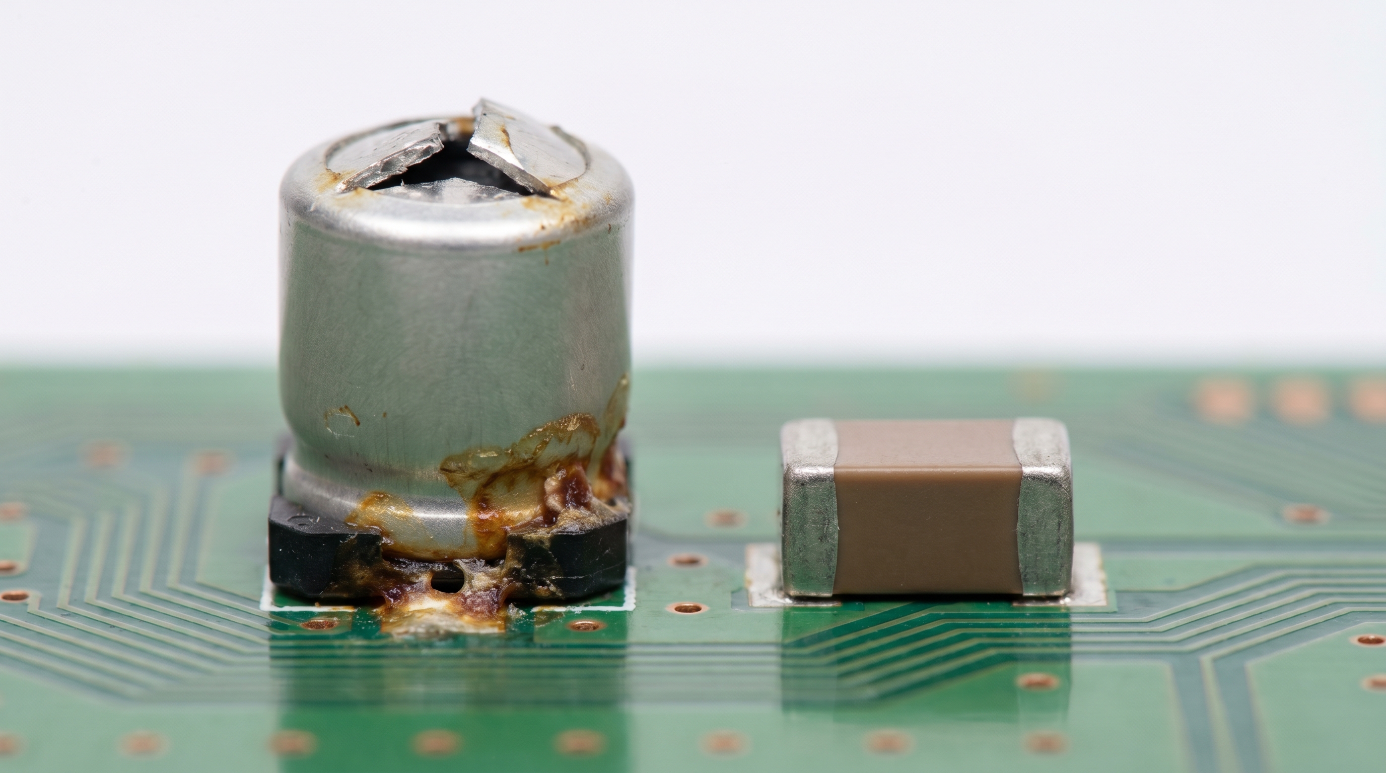
Why Do Low-End Capacitors Fail Under Heat?
Electrolytic capacitors are highly sensitive to thermal stress, and using low-grade variants is a recipe for early system failure. Low-quality capacitors feature high internal resistance and volatile liquid electrolytes that dry out rapidly when exposed to elevated temperatures. But here is the kicker: as the electrolyte evaporates, the capacitor’s ESR rises, forcing it to generate more heat during ripple filtering operations. This feedback loop quickly leads to physical bulging, leaking, and eventual total circuit failure.
- Electrolyte Dry-Out: High heat evaporates the liquid electrolyte in low-grade capacitors, permanently degrading filtering capacity.
- High ESR Loops: Increasing Equivalent Series Resistance causes the capacitor to dissipate more power as heat under load.
- Magnetic Core Saturation: Inexpensive transformer cores saturate easily, leading to high magnetic losses and rapid thermal rise.
Key Takeaway: Specifying power adapters that utilize Japanese solid-state polymer capacitors and certified industrial transformers ensures long-term operational reliability. These premium components are rated for continuous operation at
105∘C
or higher, maintaining stable electrical properties even under demanding environmental conditions.
| Component Type | Low-End Standard | Premium Industrial Standard | Thermal Lifespan Difference | |
|---|---|---|---|---|
| Output Capacitors | Liquid electrolyte (85∘C rated) | Solid polymer (105∘C rated) | 4x longevity under high thermal stress | |
| Transformer Wire | Class A enamel wire (105∘C) | Class H triple insulated wire (180∘C) | Prevents insulation melt under peak load | |
| PCB Copper Thickness | 1 oz copper layer | 2 oz or 3 oz heavy copper | Lowers board resistance, reducing PCB heat |
Our B2B material comparison below outlines the structural differences between low-grade and industrial-grade power adapter components.
Why Does Power Adapter Overheating Affect Battery Performance?

Power adapter overheating affects battery performance by introducing unstable charging voltages and conductive thermal energy that degrade the electrochemical structure of the connected battery. When an adapter runs too hot, its voltage regulation becomes unstable, causing the battery charging controller to cycle repeatedly between charging states. This continuous electrical fluctuation can lead to power adapter overheating that shortens the overall lifecycle of your device’s lithium-ion cells. Over time, these thermal anomalies reduce the battery’s maximum holding capacity.
Additionally, the copper core of the power delivery cable acts as an efficient conduit for thermal energy, carrying heat from the adapter straight to the device’s internal battery chamber. Exposure to temperatures above
40∘C
significantly accelerates the degradation of lithium-ion batteries, leading to permanent capacity loss and internal resistance build-up. In worst-case scenarios, this continuous exposure can cause battery swelling or trigger thermal runaway events. Preventing these issues requires using thermal-stable charging systems across all operations.
How Does Continuous Heat Accelerate Battery Aging?
Lithium-ion batteries rely on delicate chemical reactions to store and release energy, and these reactions are highly sensitive to external thermal stress. Prolonged exposure to high temperatures accelerates the degradation of the battery’s solid electrolyte interphase (SEI) layer, increasing internal resistance. Here is why that matters: a battery charged with a boiling-hot adapter is degrading down to a fraction of its design life with every charging cycle. This chemical breakdown eventually prevents the battery from holding a stable charge.
- SEI Layer Breakdown: High temperatures degrade the protective anode coating, increasing internal resistance and decreasing capacity.
- Lithium Plating: Thermal stress can cause lithium metal to plate onto the anode during fast charging, posing short-circuit risks.
- Swelling Hazards: Degraded battery chemicals release gas under heat, causing physical battery swelling that damages the device case.
Key Takeaway: Sourcing power adapters that deliver precise, low-ripple voltages keeps both the adapter and the connected battery operating in a cool, efficient state. This systemic thermal protection extends the operational lifespan of your mobile devices, handheld terminals, and mission-critical medical gear, minimizing replacement costs.
| Battery Temperature | Capacity Retained (500 cycles) | Internal Resistance Rise | Safety Hazard Potential | |
|---|---|---|---|---|
| 20∘C to 25∘C (Ideal) | 85% to 90% | Minimal (<5%) | Very Low (Standard operation) | |
| 35∘C to 45∘C (Moderate) | 60% to 70% | Significant (35%) | Low-Medium (Accelerated aging) | |
| >55∘C (Extreme Thermal Stress) | <40% | Extreme (>100%) | High (Swelling and potential ignition) |
The dataset above highlights the physical effects that power supply thermal fluctuations have on lithium-ion battery lifecycles.
How Can Voltage Mismatch Trigger Power Adapter Overheating?
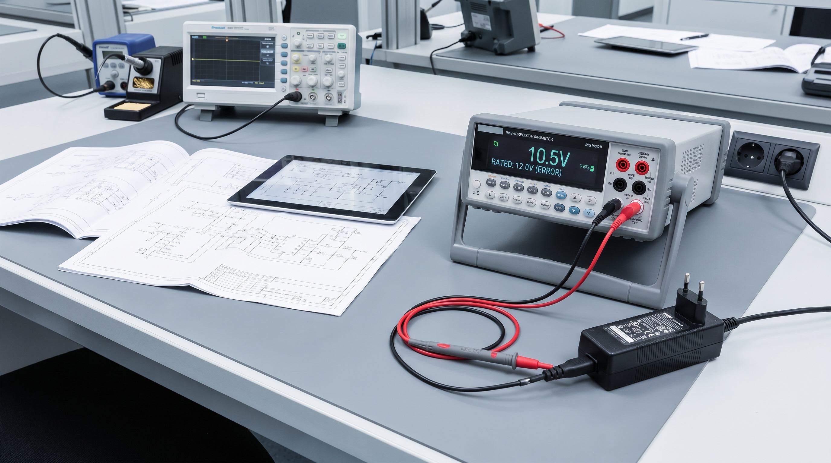
Voltage mismatch triggers power adapter overheating by forcing the internal regulation circuitry to work outside its designed efficiency curve, causing massive energy losses that dissipate as heat. When you connect an adapter with a lower voltage rating than the device requires, the device will draw excessive current to satisfy its power demands. This excessive current draw overloads the primary-side components, triggering power adapter overheating that can permanently damage the adapter’s internal electronics. Conversely, using a higher voltage adapter can overload the device’s internal buck converters, creating localized heat islands.
This mismatch often occurs when procurement teams use generic, multi-voltage adapters across diverse device fleets without verifying specific voltage parameters. The resulting electrical mismatch strains the feedback loops and increases the switching frequency of the power controllers. This strain causes the adapter to dissipate excess energy as thermal waste rather than clean electrical power. Eliminating this risk requires strict standardization of power supply parameters across your organization.
Why Does a Voltage Deficit Drive Up Current Draw?
Since electrical power is the product of voltage and current (
P=V×I
), any decrease in supply voltage forces the connected device to draw more current to maintain its power level. This increased current flow places a severe strain on the adapter’s secondary rectifier and filtering stages, which are not rated for such high current densities. Think about it: as current spikes, conduction losses grow exponentially, creating a rapid thermal rise within seconds. This process can quickly cause the adapter’s transformer insulation to melt.
- Current Compensation: Connected devices draw higher current to compensate for a lower voltage input, overloading the adapter.
- Controller Strain: Feedback loops are forced to operate at extreme duty cycles, increasing switching and conduction losses.
- Dynamic Overdrive: Device charging circuits operate continuously at peak rates, generating heat in both the power supply and the device.
Key Takeaway: Always verify that your power supply’s output voltage matches your device’s input requirements exactly before deploying hardware in the field. This strict parameter matching keeps the adapter’s conversion efficiency high and keeps operating temperatures low, preventing unexpected thermal shutdowns.
| Connection Configuration | Voltage Status | Thermal Profile | System Reliability Outcome | |
|---|---|---|---|---|
| Exact Parameter Match | 12V Adapter to 12V Device | Cool, stable operation | High longevity, normal MTBF | |
| Under-Voltage Supply | 9V Adapter to 12V Device | Rapid thermal overload | Adapter over-current cutoff or burn out | |
| Over-Voltage Supply | 15V Adapter to 12V Device | Localized heat in device | Device motherboard circuit failure |
The electrical matrix above shows the thermal consequences of pairing mismatched voltage adapters with standard device payloads.
What Safety Risks Are Linked to Power Adapter Overheating?
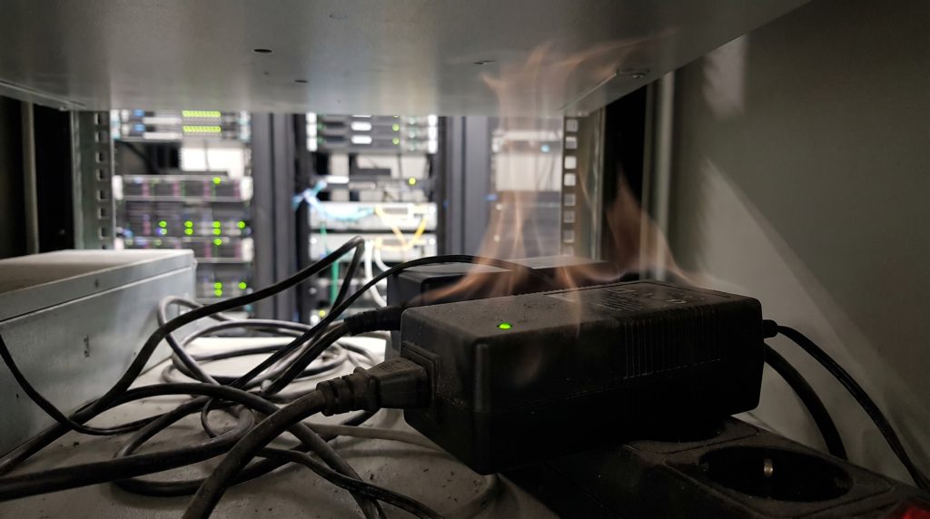
The safety risks linked to power adapter overheating include severe fire hazards, catastrophic component fires, structural enclosure melting, and potential electrical shock hazards for users. When an adapter experiences thermal runaway, the internal temperature can rise high enough to melt the plastic housing and expose live AC mains voltage. If this happens, your operators are exposed to severe shock risks, and nearby flammable materials are in danger of ignition. Unmanaged power adapter overheating remains a leading cause of commercial facility fires and hardware liabilities.
Furthermore, extreme thermal failures can vaporize conformal coatings and solder flux inside the adapter, releasing toxic smoke and fumes into the workplace. These chemical vapors are highly corrosive and can irritate the eyes and respiratory systems of nearby workers. In industrial settings, a single adapter fire can spread rapidly through cable trays, causing widespread damage and long downtime. Implementing strict safety standards and certified power adapters is the only way to eliminate these operational liabilities.
How Can High Temperatures Lead to Electrical Arcing?
At extreme temperatures, the internal plastic barriers and circuit board substrates can degrade, forming a carbonized path that conducts electricity. This carbon path can bridge the gap between primary and secondary circuits, leading to high-voltage electrical arcing across the board. Here is why that matters: once an electrical arc forms, it creates a plasma channel that burns at thousands of degrees, igniting the plastic shell in seconds. This critical safety failure is why high-quality insulation and physical spacing are so important.
- Carbon Tracking: Thermally degraded polymers turn into conductive carbon paths, allowing high-voltage arcing to occur.
- Enclosure Ignition: Non-rated plastics can catch fire easily when exposed to direct contact with overheated internal components.
- Insulation Breakdown: Transformer wire coatings fail at high temperatures, causing primary-to-secondary short circuits.
Key Takeaway: Standardizing on power adapters with certified flame-retardant enclosures (UL 94 V-0) and built-in thermal fuses protects your facilities from catastrophic fire hazards. These certified safety components automatically disconnect primary AC power before the unit reaches dangerous melting temperatures.
| Thermal Safety Hazard | Physical Root Cause | Danger Level | Engineering Solution | |
|---|---|---|---|---|
| Enclosure Melting | External casing reaches >110∘C | Severe (Exposes mains voltage) | Use high-temp PC with UL 94 V-0 ratings | |
| Flame Ignition | Internal components exceed auto-ignition temps | Extreme (Spreads fire to building) | Integrate internal primary-side thermal fuses | |
| Voltage Arcing | Carbon tracking on degraded FR4 PCB board | Severe (Destroys downstream gear) | Design boards with physical isolation gaps |
Our B2B risk assessment table above outlines the primary safety hazards associated with unmitigated power supply overheating.
How Can Manufacturers Prevent Power Adapter Overheating?

Manufacturers prevent power adapter overheating by using highly efficient Switched-Mode Power Supply (SMPS) topologies, premium thermal interface materials, and active heat dissipation designs like custom heatsinks. Leading manufacturers utilize GaN (Gallium Nitride) semiconductors, which exhibit much lower switching resistance and generate up to
50%
less heat than traditional silicon. By optimizing these internal layouts, they eliminate power adapter overheating risks at the design phase. This proactive design philosophy is the foundation of high-reliability industrial power supplies.
In addition to advanced semiconductors, premium manufacturers use fully encapsulated thermal potting compounds that transfer heat away from hot internal components to the outer shell. This uniform heat transfer lowers component operating temperatures and prevents localized hotspots from forming on the circuit board. These engineering choices ensure that the power supply can deliver stable, continuous power under high ambient temperatures. Partnering with manufacturers who prioritize these thermal designs is essential to securing your hardware investments.
Why Is Gallium Nitride Key to Cooler Power Adapters?
Gallium Nitride (GaN) features a wider bandgap than standard silicon, allowing it to handle higher voltages and switch currents at much higher speeds. This high efficiency drastically reduces switching and conduction losses, allowing manufacturers to build smaller power adapters that generate far less heat under load. Think about it: a GaN-based adapter can deliver twice the power density of a silicon adapter while operating at significantly lower internal temperatures. This thermal efficiency makes GaN the new gold standard for industrial power units.
- GaN Semiconductors: High-efficiency switching elements that reduce power conversion losses and heat output by up to half.
- Thermal Potting: High-density potting compounds that seal internal components and transfer heat evenly to the outer shell.
- Extruded Aluminum Heatsinks: Maximizes the surface area available for passive convective heat transfer.
Key Takeaway: Selecting power adapters built with GaN technology and advanced thermal potting compounds ensures your hardware runs cool, even in high-temperature environments. This thermal design margin directly translates to longer system lifespans, fewer field failures, and lower overall operating costs for your organization.
| Cooling Technology | Material Used | Core Working Principle | System Efficiency Gain | |
|---|---|---|---|---|
| GaN Switching Power | Gallium Nitride crystal | Lowers semiconductor internal resistance | +5% to +8% efficiency gain | |
| Active Thermal Potting | Thermally conductive silicone resin | Conducts internal heat evenly to the casing | 35% lower core temperatures | |
| Anodized Aluminum Finning | Custom extruded aluminum | Expands passive surface convective areas | 40% improvement in heat release |
The manufacturing table above shows the primary thermal management technologies used in premium B2B power adapters.
When Should You Replace a Power Adapter Overheating Frequently?
You should replace a power adapter overheating frequently when you observe physical enclosure warping, discoloration of the outer shell, audible high-frequency whining, or unstable voltage outputs during standard operations. These physical and electrical symptoms indicate that the internal components have suffered irreversible thermal degradation. Continuing to use an adapter in this degraded state increases your risk of sudden power adapter overheating failures that can destroy your downstream equipment. Replacing these units immediately is the only way to ensure the safety and reliability of your hardware deployments.
In many cases, the cost of replacing a compromised power adapter is a fraction of the cost of repairing a damaged downstream device. Proactive replacement schedules prevent unexpected downtime and protect your field operators from electrical and fire hazards. Standardizing on high-quality replacement adapters with verified thermal safety features ensures your systems remain online and operational. Taking action before a total failure occurs is a fundamental best practice for system administrators.
How Can You Identify Internal Thermal Degradation Early?
While some thermal damage is invisible from the outside, several clear warning signs indicate that your power adapter is failing internally. One of the most common signs is a high-pitched acoustic whining sound, which is caused by loose transformer windings vibrating under thermal stress. But here is the kicker: if you ignore these subtle warning signs, the adapter will continue to degrade until it suffers a catastrophic short circuit. Conducting regular visual and electrical audits helps you catch these issues before they cause damage.
- Acoustic Whining: High-frequency vibrations in the transformer core indicate that the internal structure has been compromised by heat.
- Substrate Discoloration: Darkening of the outer plastic shell or PCB substrate indicates that the adapter is operating at dangerous temperatures.
- Voltage Fluctuation: Intermittent power dropouts or output voltage drift indicate that the voltage regulation feedback loop is failing.
Key Takeaway: Establishing a proactive replacement schedule based on operational runtime and environmental conditions prevents costly, unexpected field failures. By replacing overheating adapters with high-efficiency, certified units immediately, you protect your connected equipment and maintain absolute system uptime.
| Diagnostic Sign | Failure Risk Level | Root Internal Issue | Recommended Immediate Action | |
|---|---|---|---|---|
| Warped Casing / Odor | Extreme Risk | Plastic shell softening; internal melting | Shut down power; replace unit immediately | |
| High Acoustic Whine | Medium-High Risk | Transformer core or winding separation | Schedule replacement within 48 hours | |
| DC Voltage Fluctuations | High Risk | Output filtering capacitor degradation | Replace adapter before next operational shift |
Our B2B diagnostic evaluation table below shows the key warning signs and recommended actions for aging or overheating power units.
Conclusion
Understanding the thermal mechanics behind power supply design is critical to ensuring the longevity, safety, and efficiency of your enterprise hardware deployments. As analyzed throughout this guide, overheating is not simply a localized inconvenience—it is a clear indicator of systemic inefficiencies, material wear, or physical limits that can compromise valuable downstream electronic systems. By selecting power adapters with advanced thermal architectures, heavy-duty components, and proper certifications, you eliminate these high-risk failure modes before they result in expensive downtime or structural hazards.
At Merryking Electronics, we specialize in manufacturing premium, high-reliability OEM/ODM power supplies designed to operate flawlessly under the most demanding workloads. Our systems feature Gallium Nitride (GaN) engineering, solid-state polymer filtering, and active thermal protection circuits to keep your infrastructure running cool and secure. Don’t let thermal failures compromise your hardware reputation or project timelines. To consult with our senior application engineers on custom thermal designs or to request samples of our certified, high-reliability systems, contact us today and secure your power infrastructure.
Frequently Asked Questions
Can I use a higher-wattage adapter to reduce heat?
Yes, you can. A higher-wattage adapter will only deliver the power required by the connected device, meaning it operates well below its maximum capacity. Running at lower load factors decreases internal electrical stress and heat generation, resulting in a cooler, longer-lasting power supply.
What’s the best way to cool down a hot adapter quickly?
No, you should never use artificial rapid cooling methods. Subjecting a hot power adapter to cold air streams or refrigerated environments can cause rapid thermal contraction, leading to micro-fractures in solder joints or ceramic capacitors. The best method is to disconnect primary power, remove any physical obstructions, and allow natural convective airflow to cool the adapter down safely.
How do I know if the heat is coming from the adapter or from the device it is powering?
Yes, you can isolate the heat source with a simple test. Disconnect the adapter from the device and let it remain plugged into the AC wall outlet in an idle state. If the adapter continues to run hot, the issue is caused by internal component wear or excessive idle losses within the adapter itself; if it cools down completely, the connected device is drawing more current than designed.
Can I swap adapters between devices of different brands if the connectors match?
No, it is highly discouraged to swap adapters without verifying compatibility. Matching physical plug geometry does not guarantee that the voltage, current ratings, or polarity configurations are compatible with your device. Connecting a mismatched adapter risks severe electrical overloading, leading to immediate thermal runaway or circuit failure.