Reducing power adapter defect rates requires a transition from reactive testing to a comprehensive, multi-stage quality control strategy spanning design, component sourcing, automated assembly, and rigorous testing. As a B2B procurement manager or hardware engineer, you have likely faced the nightmare of unexpected field failures and customer returns. A high power adapter defect rate doesn’t just trigger expensive RMA logistics; it permanently destroys customer trust, ruins major retail product launches, and risks catastrophic safety recalls. The solution is not to simply cross your fingers, but to partner with manufacturers implementing strict, proactive quality gates from incoming materials to final functional tests.
Think about it: A 1% failure rate in your office means a 100% loss of confidence for your most critical enterprise accounts. Let’s look at how to drive that rate down to near-zero.
What Causes a High Power Adapter Defect Rate?
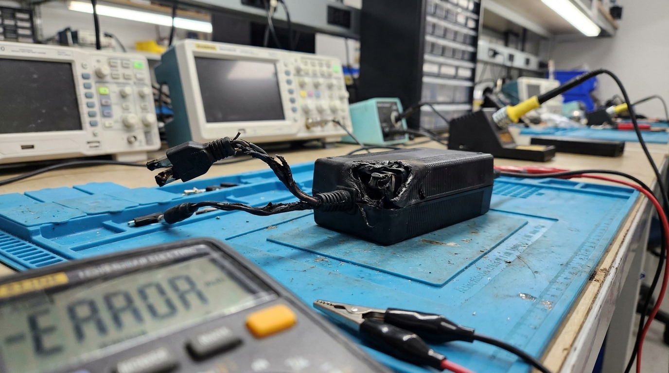
High power adapter defect rates are caused by a combination of thermal stress, inadequate protective circuit design, and poor manufacturing execution. When these vectors align, your product fails prematurely in the field.
Understanding these root failures is the first step toward securing your supply chain stability. Let’s look closer at where things break.
Thermal Stress and Component Wear-out
Think about it: when an adapter runs at high temperatures, its internal components degrade at an accelerated rate. Electrolytic capacitors are especially susceptible to heat-induced dry-out over time.
If the thermal dissipation layout is poorly designed, junction temperatures on key semiconductors will quickly exceed safe operational thresholds. This degradation leads to sudden component shutdown or structural failure.
- Capacitor liquid electrolyte dry-out under sustained temperatures over 105°C.
- Semiconductor thermal runaway caused by inadequate heat-sinking.
- Localized hot spots degrading nearby sensitive electronic components.
Inadequate Protective Circuit Design
Let’s face it: cheap adapters often sacrifice protective features to save pennies on the bill of materials. Lacking active over-voltage, over-current, and over-temperature protection guarantees field failures during minor power surges.
Furthermore, if the design neglects ESD protection paths, user contact can immediately fry internal chips. This oversight leaves your entire electrical system vulnerable to erratic main-line voltage shifts.
- Absence of robust metal-oxide varistors (MOVs) to absorb transient power surges.
- Lack of thermal shutdown circuits to prevent overheating hazards.
- Poor electrostatic discharge layout causing micro-controller lockups.
Substandard PCB Assembly and Soldering
Here is the kicker: manual soldering of heavy parts like transformers often leads to cold solder joints and micro-cracks. These physical flaws will eventually sever electrical connections under thermal cycling.
Standard automated SMT lines must run optimized profiles to prevent micro-voids in heat-sink solder layers. Without these precautions, mechanical stress during shipping will break the connections.
- Cold solder joints causing intermittent electrical connections.
- Solder voids on thermal pads trapping high heat inside components.
- Delamination of printed circuit boards due to incorrect reflow heat cycles.
| Failure Root Cause | SMT/Manufacturing Level | Observed Field Symptom | Preventive Measure | |
|---|---|---|---|---|
| Solder Joint Voiding | Poor reflow profile in SMT | Intermittent power connection | Automated 3D X-Ray Inspection | |
| Capacitor Dry-out | Low-grade component selection | Output voltage ripple / No boot | Specifying ≥5,000 hours at 105∘C | |
| Transformer Breakdown | Poor wire winding isolation | High leakage current / Shock hazard | Routine Hi-Pot testing on production lines |
This matrix demonstrates that early structural intervention is the only way to avoid complex field repairs.
Key Takeaway: Identifying and addressing component wear-out and soldering flaws early protects your margins and saves your customer support team from catastrophic RMA surges.
Why Does Power Adapter Defect Rate Matter for B2B Buyers?

The power adapter defect rate matters to B2B buyers because it directly impacts your overall operational costs, brand reputation, and regulatory compliance. Every failed adapter represents an expensive point of friction in your distribution pipeline.
If you ignore these compounding variables, the downstream financial damage can easily wipe out your initial unit margins. Let’s look at the actual breakdown of these risks.
The Hidden Financial Toll of RMAs
Think about it: replacing a single five-dollar adapter can cost you more than one hundred dollars in logistics. You have to pay for return shipping, custom duties, diagnosis time, and replacement dispatch.
This hidden tax eats your profits quietly while pulling valuable engineering resources away from new development. It turns a cheap purchase into a long-term liability.
- Two-way international shipping fees for returning and replacing defective goods.
- Engineering laboratory labor hours spent diagnostic-testing field failures.
- Delayed project rollouts causing contractual penalties and customer friction.
Severe Reputation and Account Loss Risks
Let’s face it: your clients view the power supply as the heart of your electronic system. When the adapter fails, your entire product is dead in the eyes of the end-user.
This means you risk losing multi-million dollar corporate accounts over a tiny, poorly soldered component. Once trust is broken in the enterprise world, it is almost impossible to earn back.
- Direct degradation of your brand’s quality reputation in trade communities.
- Rapid customer churn from critical system downtime in medical or enterprise sectors.
- Negative online reviews eroding long-term marketing efforts and trust.
Regulatory and Legal Compliance Liabilities
Here is the kicker: a defective power unit is more than just inconvenient; it can be an electrical safety hazard. Failed insulation can cause shock or fire, triggering mandatory regulatory reporting.
Ensuring your supplier meets strict international safety standards protects you from devastating legal battles. Compliance is your shield against catastrophic corporate liability.
- Violations of UL, CE, FCC, RoHS, and PSE certification protocols.
- Costly class-action recalls mandated by government safety commissions.
- Legal liabilities stemming from property damage or electrical shock injuries.
| Business Impact Area | Primary Financial Risk | Brand Impact Severity | Long-Term Mitigation Strategy | |
|---|---|---|---|---|
| RMA Logistics | High transport & replacement cost | Low (Operational) | Tighten supplier AQL standards | |
| Client Churn | High loss of recurring contracts | Critical (Marketplace) | Transition to verified premium manufacturers | |
| Legal Recalls | Extreme regulatory fines & damages | Severe (C-Suite level) | Enforce 100% safety testing on assembly lines |
This business impact model underscores why cheap adapters are always the most expensive option in the long run.
Key Takeaway: Protecting your B2B enterprise from margin erosion requires prioritizing quality metrics over short-term savings during vendor selection.
How Can Material Inspection Lower Power Adapter Defect Rate?
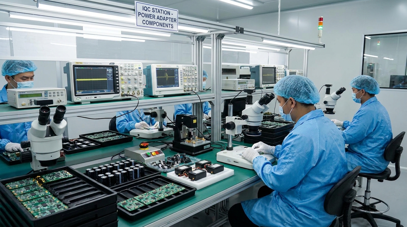
Incoming Quality Control (IQC) reduces the power adapter defect rate by intercepting faulty electronic components before they ever reach the assembly line. Catching bad silicon or fragile plastics at the loading dock prevents massive rework costs.
This structural gate ensures your factory works only with verified, high-performance inputs. Let’s explore how a strong incoming inspection system is set up.
Strict IQC Sampling Protocols
Think about it: inspecting every single incoming resistor is impossible for high-volume manufacturing. That is why a reliable factory must use standardized statistical sampling models like ANSI/ASQ Z1.4.
This mathematical baseline sets clear boundaries for major and minor defects. It allows inspectors to clear or reject whole batches with maximum confidence.
- Applying Critical (0), Major (1.0), and Minor (2.5) Acceptable Quality Limits.
- Randomized container inspections to ensure consistent component quality.
- Instant quarantine of any component batch that violates preset limits.
Verification of Core Component Parameters
Let’s face it: you cannot trust component specifications written on cardboard boxes. Expert IQC technicians must actively measure raw parameters like MOSFET resistance and capacitor leakage currents.
Skipping these electrical checks allows substandard parts to slip into the wave soldering line. Once soldered, these bad components are much harder and more expensive to isolate.
- Testing MOSFET on-state resistance and actual breakdown voltage limits.
- Measuring capacitor Equivalent Series Resistance (ESR) to prevent signal noise.
- Verifying magnetic core permeability on custom-wound power transformers.
Supplier Auditing and Continuous Scorecards
Here is the kicker: a single bad supplier can throw your entire assembly line into chaos. Enforcing regular audits and scoring vendors on delivery quality keeps them honest and focused on performance.
This collaborative oversight builds a transparent and robust raw material ecosystem. It forces sub-tier component manufacturers to meet your exact safety limits.
- Annual facility audits of primary semiconductor and plastic suppliers.
- Monthly supplier scorecards tracking defect counts and delivery delays.
- Diversified sourcing of critical components to bypass sudden vendor failures.
| Component Group | Critical IQC Test Parameters | Targeted SMT Defect Prevented | Sampling Plan Standard | |
|---|---|---|---|---|
| Power MOSFETs | Breakdown voltage & RDS(on) | Sudden short circuit failure | ANSI/ASQ Z1.4 Level II | |
| Electrolytic Caps | ESR & DC Leakage current | Output voltage noise & ripple | Zero-Defect (c=0) Sampling | |
| Transformers | Insulation dielectric strength | Ground leakage & shock hazard | 100% Lot Sample Verification |
This robust defensive perimeter ensures that only pristine building blocks enter the production environment.
Key Takeaway: Demanding verified IQC records from your manufacturing partner guarantees that your adapters are built from the highest-quality raw materials.
How Does PCB Assembly Quality Affect Power Adapter Defect Rate?
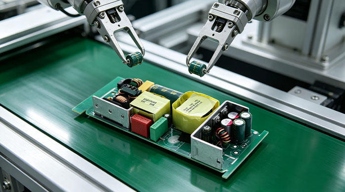
PCB assembly quality directly dictates the power adapter defect rate because automated precision prevents component misalignment, open joints, and ESD damage. The surface mount technology (SMT) line is the absolute backbone of adapter durability.
If the SMT process is sloppy, the product’s lifespan is drastically reduced from day one. Let’s review the required tools for precision robotic assembly.
3D Solder Paste Inspection and Reflow
Think about it: a perfect solder joint begins with the exact amount of solder paste. Utilizing 3D Solder Paste Inspection (SPI) checks height and volume before any components are placed.
This automated precision eliminates joint starvation and bridging defects before heating occurs. It guarantees that the foundations of your electrical connections are structurally sound.
- Real-time monitoring of paste volume to avoid dry joints.
- Precise temperature profiling for lead-free SAC305 solder alloys.
- Preventing thermal shock to delicate ceramic chip capacitors.
Automated Optical Inspection Integration
Let’s face it: human inspectors get tired and miss microscopic alignment flaws. Implementing automated optical inspection (AOI) before and after reflow ovens ensures every component sits perfectly.
These high-speed cameras compare every board against a digital gold standard. Any offset is flagged instantly for correction before moving to final assembly.
- Immediate detection of tombstoned or misaligned micro-components.
- Checking solder fillet quality to guarantee long-term joint strength.
- Automated rejection of boards showing bridge shorts or missing pieces.
Rigid ESD and Moisture Controls
Here is the kicker: electrostatic discharge is an invisible killer of microchips. A single static shock can weaken a component, leading to mysterious failures months down the line.
Implementing continuous monitoring and humidity control prevents these quiet disaster scenarios. It protects sensitive semiconductors from early field degradation.
- Mandatory grounded wrist strap systems for all line workers.
- Humidity-controlled dry cabinets for moisture-sensitive parts.
- ESD-safe flooring and conductive storage bins throughout assembly.
| SMT Quality Step | Technology Employed | Primary Defect Avoided | Yield Improvement | |
|---|---|---|---|---|
| Solder Inspection | 3D SPI Systems | Solder bridging & starved joints | +1.5% First Pass Yield | |
| Component Placement | High-Speed Robotic Pick-and-Place | Tombstoning & misalignment | +2.2% Assembly Efficiency | |
| Post-Reflow Check | Dual-Side 3D AOI Cameras | Cold soldering & missing parts | +3.0% Final Board Quality |
This technical flow shows how robotic precision replaces unreliable human observation to maintain steady assembly quality.
Key Takeaway: Ensuring your manufacturer operates state-of-the-art 3D SPI and AOI systems protects your devices from subtle structural weaknesses.
How Does Burn-In Testing Reduce Power Adapter Defect Rate?
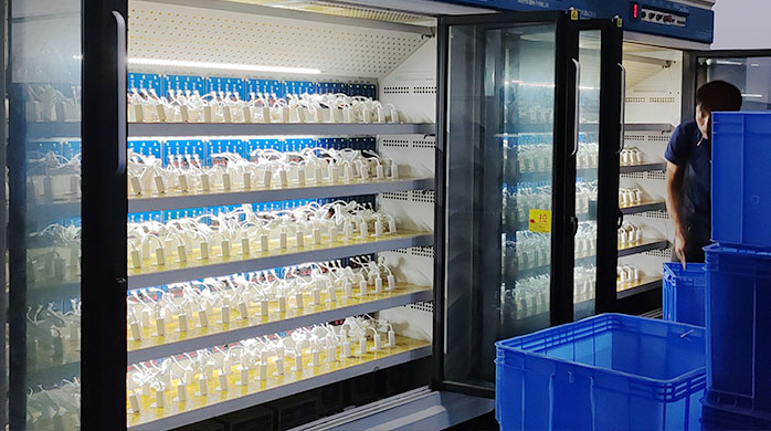
Burn-in testing minimizes the power adapter defect rate by filtering out early-stage “infant mortality” component failures under continuous thermal stress. By subjecting every unit to harsh operating conditions, weak components fail inside the factory, not in your customer’s office.
This active screening process separates highly reliable power supplies from ticking time bombs. Let’s break down how this thermal baking works.
Eliminating Infant Mortality Failures
Think about it: electronic component failure rates follow a classic “bathtub curve.” They fail either very early in their lifespan or much later due to natural wear-out.
Running adapters under full load forces those weak units to break before shipment. This step prevents early failures from damaging your end-users’ hardware.
- Accelerating latent semiconductor crystal defects to actual failure.
- Identifying weak capacitor seals that would fail under early use.
- Filtering out marginal assembly errors under dynamic heat cycles.
Optimal Temperature and Stress Profiles
Let’s face it: a simple room-temperature test does not simulate real-world workloads. Adapters must be baked in specialized chambers at temperatures up to 45°C under maximum rated loads.
This thermal pressure exposes design and manufacturing limits with extreme accuracy. It ensures your power supplies run safely in restricted enclosure spaces.
- Baking units for 2 to 4 hours at elevated temperatures.
- Applying 100% rated electrical loads to test continuous thermal capacity.
- Using accelerated stress testing for high-reliability medical gear.
Real-Time Monitored vs. Static Burn-In
Here is the kicker: cheap factories use static burn-in setups where they check units only after the cycle ends. If an adapter fails temporarily during the heat wave and self-recovers, they miss it entirely.
Monitored burn-in systems log output performance continuously to catch these intermittent faults. This level of tracking is essential for mission-critical enterprise systems.
- Continuous computer tracking of output voltage drops under stress.
- Instant automatic shut-off and flagging of failing channels.
- Comprehensive digital history reports linked to each serial number.
| Burn-In Method | Thermal Environment | Load Profile | Diagnostic Quality | |
|---|---|---|---|---|
| Static Burn-In | Ambient Room Temp | Static Resistive Load | Low (Misses intermittent drops) | |
| Chamber Burn-In | 40∘C−45∘C Room | 100% Continuous Load | Medium (Good for general units) | |
| Monitored Dynamic | Controlled Thermal Room | Programmed Duty Cycles | High (Catches real-time voltage sags) |
This testing hierarchy demonstrates why active, real-time monitoring is superior to passive thermal baking.
Key Takeaway: Insisting on monitored dynamic burn-in testing ensures that infant mortality failures are systematically removed before shipping to your warehouse.
How Can Hi-Pot and ATE Testing Lower Power Adapter Defect Rate?
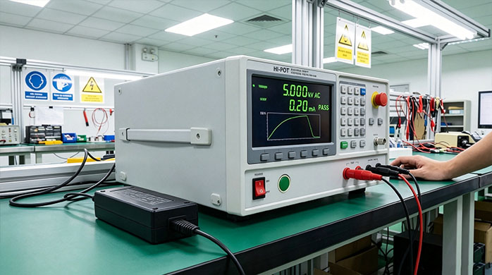
Implementing Hi-Pot and ATE testing lowers the power adapter defect rate by ensuring perfect high-voltage insulation and automated functional performance. These computerized validation stations remove human error from the final inspection process.
Every single power supply must satisfy these precise electrical standards before packaging. Let’s study how these automatic steps are executed.
Hi-Pot Electrical Safety Verification
Think about it: high-voltage isolation testing is the only way to prove a user will not receive an electric shock. Applying up to 3000VAC between primary and secondary circuits verifies insulation integrity.
This test instantly identifies transformer breakdown or tiny spacing violations on the circuit board. It acts as an absolute safety gate for international shipping compliance.
- Enforcing 100% production-line insulation testing for safety compliance.
- Detecting minor leakage currents that exceed international safety limits.
- Preventing dangerous short-circuits under real-world mains fluctuations.
Automated Test Equipment Workflows
Let’s face it: manually checking voltage, noise, and transient response times takes too long and yields inconsistent results. Automated Test Equipment (ATE) measures these critical specifications in seconds.
This complete functional check catches minor voltage sags that humans cannot see. It guarantees steady performance under all dynamic electrical loads.
- Testing voltage accuracy and ripple under different loads.
- Measuring standby power consumption to meet strict green energy laws.
- Verifying safety threshold trigger points for over-current scenarios.
Full Data Logging and Serial Traceability
Here is the kicker: if a defect happens in the field, you need to know exactly when it was made and how it tested. Modern ATE software automatically saves every single test record by the unit’s serial number.
This detailed paper trail allows fast root-cause analysis and localized batch containment. It shields your brand from broad, unfocused field recalls.
- Saving comprehensive test files directly to a secure factory cloud.
- Providing clear compliance evidence for safety inspectors.
- Targeted recalls of isolated bad runs instead of discarding complete shipments.
| Test Category | Parameter Checked | Target Value | Testing Technology | |
|---|---|---|---|---|
| Hi-Pot Safety | Dielectric Strength | Primary-to-Secondary ≥3000VAC | Dedicated Hi-Pot Tester | |
| Functional Line | Output Voltage Stability | 5.0V±5% under load | Automated Test Equipment | |
| Signal Quality | Output Ripple & Noise | ≤50mV peak-to-peak | High-Speed Digital Oscilloscope |
This rigorous sequence provides absolute quantitative proof that every shipped adapter is safe and operational.
Key Takeaway: Confirming your supplier uses automated ATE systems shields your business from shipping failures and critical safety liabilities.
Why Do Poor Soldering & Parts Raise Power Adapter Defect Rate?
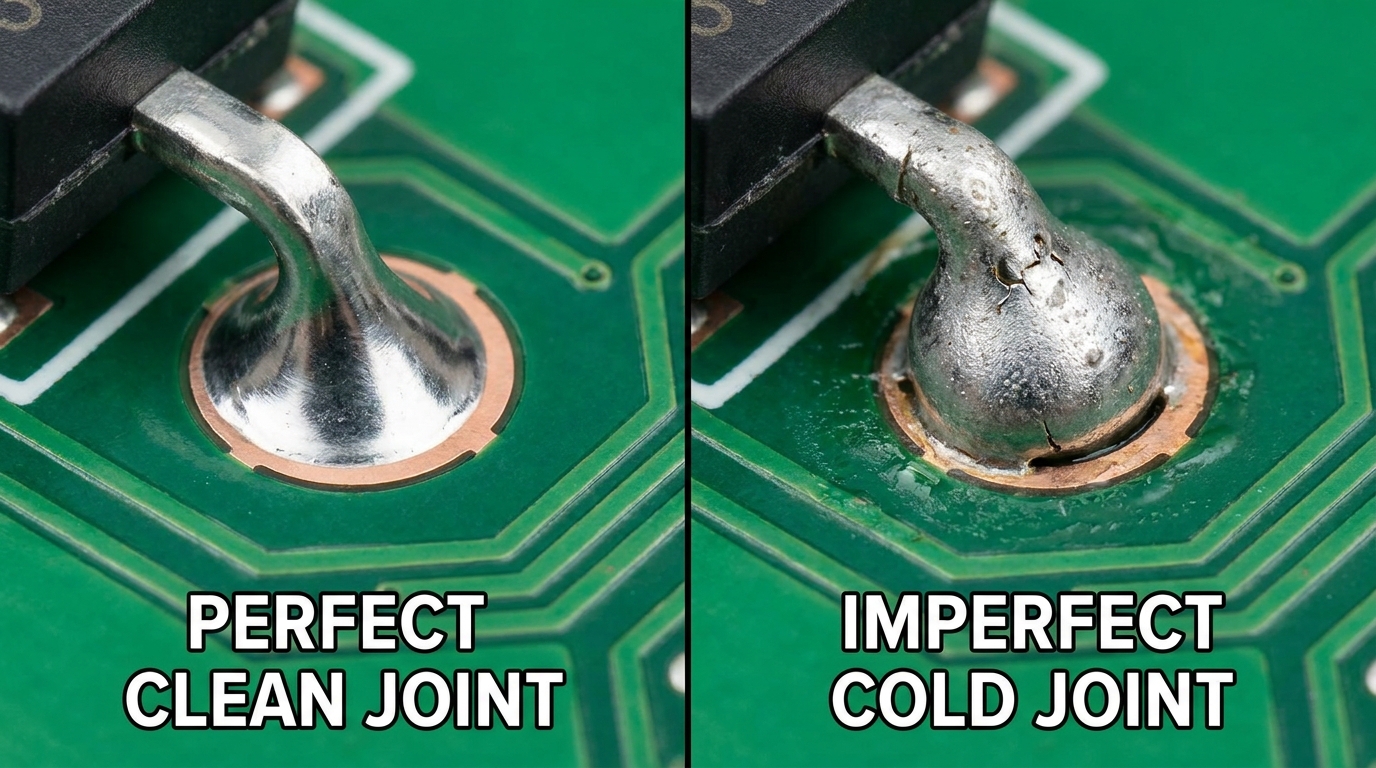
Substandard soldering and counterfeit components spike the power adapter defect rate by creating brittle mechanical joints and unpredictable electrical behavior under thermal loads. When a manufacturer cuts corners with cheap solder or unbranded components, physical failure is inevitable.
These tiny vulnerabilities quickly expand into catastrophic failure vectors once deployed. Let’s dissect how low-grade processing causes physical system degradation.
The Danger of Low-Grade Components
Think about it: using unbranded or gray-market components is a gamble that always ends in failure. Cheap MOSFETs often fail to handle current surges, while low-grade plastics warp under normal working heat.
These unstable parts lack the safety margins required for continuous high-performance operation. They make your products unreliable and highly prone to short-circuit disasters.
- Using fake semiconductors that fail under rated electrical stress.
- Sourcing off-brand capacitors that dry out in a fraction of their promised lifetime.
- Choosing brittle casing plastics that crack easily during transit or use.
Solder Micro-cracks and Intermetallic Growth
Let’s face it: lead-free soldering requires precise heat control. If the solder cools too quickly, it creates brittle intermetallic compound layers that break under mechanical vibration.
These hidden fractures eventually sever electrical connections during daily thermal expansion. This degradation leads to intermittent power drops that frustrate your end-users.
- Brittle cold solder joints failing under minor drops or bumps.
- Thick intermetallic compound growth weakening structural joint integrity.
- Micro-cracks separating component pins from copper circuit boards.
Inefficient Thermal Design Layouts
Here is the kicker: bad circuit layouts place heat-generating power resistors right next to heat-sensitive capacitors. This poor spatial design bakes vital components continuously, accelerating their decay.
Professional engineers design smart boards to isolate and dissipate intense heat safely. A smart layout is the easiest way to double your adapter’s lifetime.
- Improper spacing causing extreme heat concentration in small areas.
- Neglecting heat-sink copper planes for surface-mounted power components.
- Premature aging of electrolytic caps from surrounding high-temp areas.
| Solder Joint Status | Visual Characteristics | Mechanical Reliability | Recommended Diagnostic Method | |
|---|---|---|---|---|
| Perfect Joint | Shiny, smooth, concave fillet | High resistance to thermal stress | Automated Optical Inspection | |
| Cold Joint | Dull, grainy, rough surface | Brittle, breaks easily | 3D X-Ray & Micro-Sectioning | |
| Starved Joint | Thin coverage, pin outline visible | Low mechanical strength | Visual microscope validation |
This comparison reveals that mechanical joint integrity is just as critical as component selection for long-term survival.
Key Takeaway: Partnering with a manufacturer that uses premium, brand-name components and strict reflow control ensures your units last for years.
How Can Process Control Improve Power Adapter Defect Rate Stability?
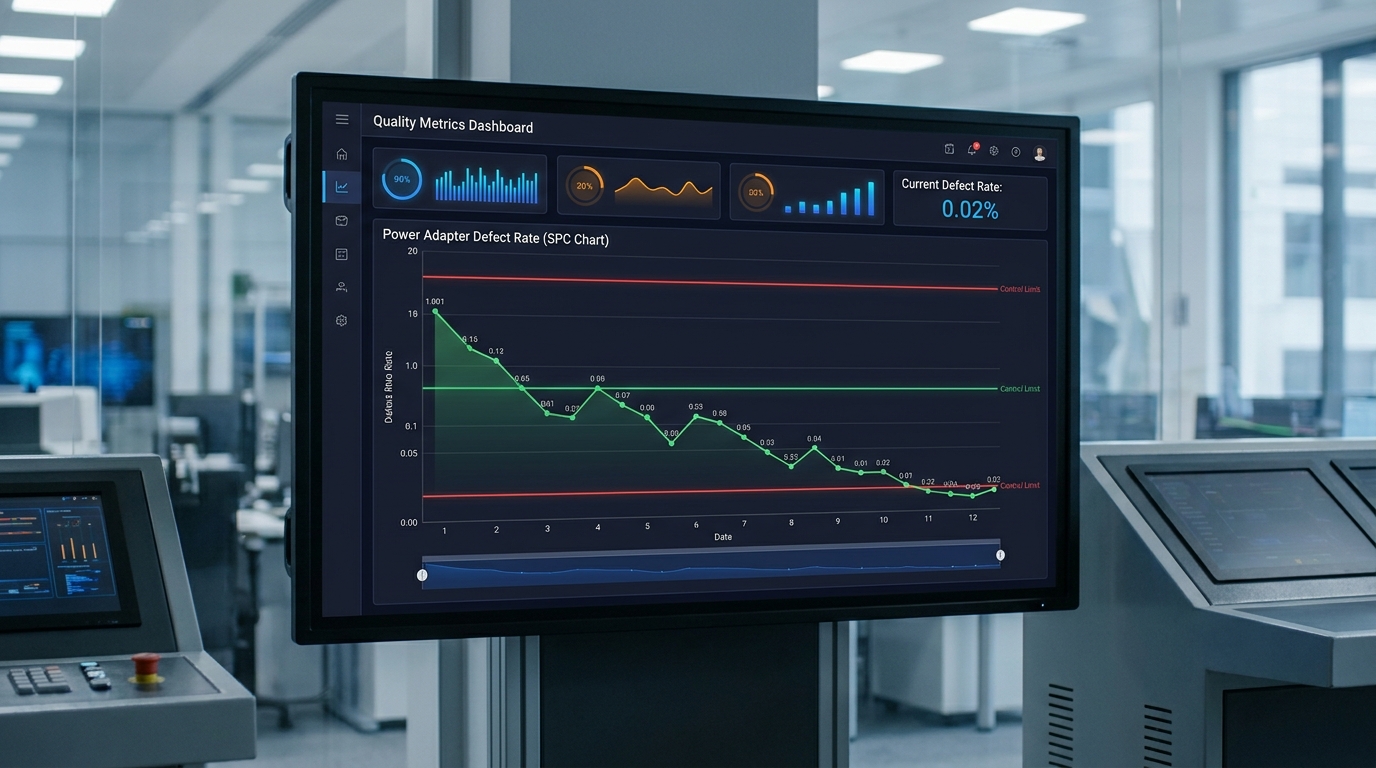
Statistical Process Control (SPC) stabilizes the power adapter defect rate by tracking real-time deviations in key assembly metrics and correcting them before defects occur. Instead of just sorting out bad adapters at the end, SPC fixes the machine drifts that cause them.
This active process tracking ensures your production quality remains perfectly level over time. Let’s see how a modern manufacturing floor manages these statistical metrics.
Statistical Process Control Implementation
Think about it: a machine’s calibration drifts naturally over thousands of production cycles. Tracking metrics like Cp and Cpk allows engineers to spot and correct these trends before products fall out of specification.
This preemptive mathematical model prevents massive batch defects from ever happening. It keeps your assembly line output exceptionally consistent.
- Using real-time control charts to track minor variations in output voltages.
- Proactively adjusting SMT nozzle calibration based on drift patterns.
- Achieving higher process capability ratings (Cpk > 1.33) for key parameters.
Operator Training and Visual Standardization
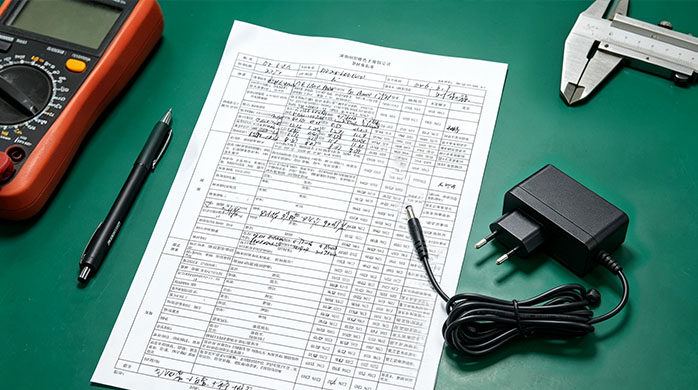
Let’s face it: human hands still perform critical assembly tasks, like inserting heavy transformer parts. Providing ongoing training and clear IPC-A-610 visual charts keeps operators focused on quality.
Simple mistake-proofing tools on the workbench help prevent errors from happening. This step bridges the gap between manual work and automated accuracy.
- Mandatory certifications for hand-soldering and component insertion.
- Clear visual posters illustrating accepted versus rejected solder fillets.
- Using physical alignment jigs to guarantee identical component placement.
Rigid Machine Preventive Maintenance
Here is the kicker: dirty SMT nozzles or poorly calibrated reflow heating zones cause erratic defect spikes. Enforcing scheduled preventive maintenance preserves machine precision across major manufacturing runs.
This continuous upkeep reduces unexpected line shutdowns and protects production quality. It is the signature habit of a professional, world-class factory.
- Daily cleaning and vacuum testing of robotic pickup nozzles.
- Monthly profiling and thermocouple calibration of reflow ovens.
- Regular wave solder bath maintenance to prevent dross buildup.
| Process Control Area | Diagnostic Tool Used | Tracking Metric | Operational Action | |
|---|---|---|---|---|
| SMT Precision | Cp / Cpk Process Capability | Placement accuracy deviation | Re-calibrate robotic feeder heads | |
| Thermal Profiling | Multi-channel Thermocouples | Temperature curve deviations | Adjust reflow oven zone power | |
| Human Operations | Visual Poka-Yoke Jigs | Operator assembly error rate | Simplify physical placement steps |
This structured control framework shifts factory operations from reactive troubleshooting to highly reliable prevention.
Key Takeaway: Auditing a factory’s SPC dashboards and maintenance schedule reveals their true commitment to long-term batch stability.
What Quality Data Helps Evaluate Power Adapter Defect Rate?
B2B buyers must evaluate first-pass yield (FPY) and MTBF calculations to determine a manufacturer’s true power adapter defect rate capability. Relying on simple promises is a recipe for expensive supply chain surprises.
Demanding raw quality data gives you the leverage to verify actual factory performance. Let’s analyze the key data points you must check.
Analyzing First Pass Yield Metrics
Think about it: a high final inspection rate does not mean a factory is running smoothly. If the First Pass Yield (FPY) is under 98%, they are doing heavy re-work behind the scenes to fix defective boards.
These repaired units carry hidden stresses that often lead to early field failures later. You want a factory that builds products right the first time.
- Targeting an SMT first-pass yield of 98.5% or higher on mass runs.
- Avoiding factories with low FPY that rely on manual solder rework.
- Tracking internal scrap rates to measure production consistency.
Deciphering MTBF and Reliability Standards
Let’s face it: some suppliers make up Mean Time Between Failure (MTBF) numbers out of thin air. You must demand calculation sheets based on real, internationally recognized standards like Telcordia or military handbooks.
These structured mathematical predictions ensure your hardware is built for long-term survival. They prove that the design actually matches its operational life target.
- Demanding MTBF data verified by Telcordia SR-332 or MIL-HDBK-217.
- Checking component temperature stress factors used in reliability math.
- Verifying design margins under worst-case environmental conditions.
Auditing Outgoing Quality Control Reports
Here is the kicker: the final gate before shipping is the Outgoing Quality Control (OQC) audit. Reviewing these reports guarantees that finished packages are inspected for cosmetic, structural, and electrical safety.
This final verification ensures your adapters arrive packaged and functioning perfectly. It is your ultimate guarantee before wiring payment.
- Confirming OQC checks packaging stability and correct labeling.
- Verifying post-packaging functional sample tests are completed.
- Reviewing cosmetic inspection logs to ensure clean plastic finishes.
| Metric Name | Minimum Acceptable Target | Reliability Importance | Sourcing Impact | |
|---|---|---|---|---|
| First Pass Yield | ≥98.5% on SMT/ATE | Shows high process consistency | Reduces latent field failures | |
| MTBF Rating | ≥100,000 hours | Predicts long-term lifetime | Lowers overall brand risk | |
| OQC Sampling | Zero Critical Defects | Prevents shipment surprises | Guarantees compliance out of box |
This quantitative score card cuts through marketing fluff to expose real manufacturing capability.
Key Takeaway: Demanding verified FPY and MTBF records before placing high-volume orders prevents you from selecting volatile, high-risk suppliers.
How Can a Top Manufacturer Reduce Power Adapter Defect Rate?
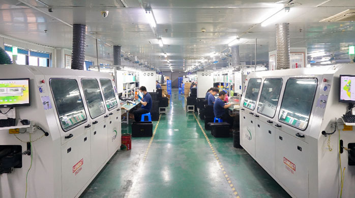
Partnering with a premier tier-one supplier minimizes your power adapter defect rate because they design out failures before mass production begins. Rather than just catching defects, a world-class factory implements proactive design reviews and tracking tools.
This advanced engineering collaboration protects your hardware launch from the start. Let’s analyze how a top factory secures your investment.
DFMEA: Preventing Sourcing Failure Modes
Think about it: the best way to prevent a production error is to make it physically impossible by design. Design Failure Mode and Effects Analysis (DFMEA) identifies and solves bottlenecks before the assembly line starts.
This deep design review removes thermal bottlenecks and tight trace spacing issues early. It saves months of diagnostic headache down the line.
- Reviewing layout designs to ensure optimal component spacing.
- Simulating thermal dissipation paths to avoid dangerous hot spots.
- Simplifying complex manual assembly steps to prevent human errors.
Board-Level QR Component Traceability
Let’s face it: when a component batch fails, you need to isolate and contain it instantly. Laser-etching unique QR codes onto every PCB allows a factory to track every resistor and capacitor back to its raw batch.
This detailed tracing capability turns a potential recall disaster into a targeted minor adjustment. It provides absolute transparency for your peace of mind.
- Scanning board codes to trace components back to raw suppliers.
- Isolating bad component batches quickly to prevent broad line halts.
- Providing clear evidence files for component safety audits.
Collaborative Feedback and Yield Optimization
Here is the kicker: quality control is an ongoing feedback loop, not a static checkpoint. Top-tier manufacturers actively analyze field return data and feed those insights directly back into design and SMT adjustments.
This continuous cycle ensures your product quality improves with every single batch produced. It creates a powerful technical alliance between buyer and builder.
- Hosting regular engineering meetings to analyze SMT yield trends.
- Adapting reflow heat settings based on field failure analysis.
- Updating circuit layout revisions to optimize long-term reliability.
| Manufacturer Support | Technical Approach | Long-Term Business Value | |
|---|---|---|---|
| DFMEA Analysis | Early design simulation and review | Prevents expensive layout revisions | |
| QR Code Tracking | Individual board component scanning | Restricts recall scopes to minor batches | |
| Continuous Optimization | Dynamic design and reflow updates | Keeps product quality improving over time |
This collaborative engineering model transitions your supplier from a basic vendor to an essential strategic partner.
Key Takeaway: Choosing a manufacturer equipped with DFMEA expertise and QR traceability safeguards your brand and guarantees near-zero field failure rates.
Conclusion
Navigating field returns, high RMA shipping fees, and safety recalls is exhausting and costly. This guide shows how structured IQC, precision PCB assembly, monitored burn-in, and automated safety testing can systematically reduce defects. A reliable factory acts as your shield, executing rigorous statistical controls and advanced co-engineering.
To elevate your product reliability and secure your supply chain, contact us today to schedule a technical audit and experience our advanced manufacturing processes firsthand.
Frequently Asked Questions
Can I trust a manufacturer that doesn’t use monitored burn-in testing?
No, because static burn-in setups often miss intermittent voltage drops that only occur during active heat cycles. Without dynamic monitoring, unstable adapters can slip through and fail shortly after deployment.
What is the best way to verify if my supplier uses genuine components?
Insist on raw material traceability records and active IQC component verification. A quality factory will gladly share their incoming quality checks and component batch tracking logs with you.
How do I know if our adapter’s failure rate is dangerously high?
Any field failure rate exceeding 1% requires immediate technical investigation. In enterprise environments, even a 0.5% failure rate can cause major reputation damage and logistical expenses.
Can automated SMT lines eliminate soldering defects completely?
Yes, when combined with 3D SPI and post-reflow AOI checking. While minor machine drift occurs, real-time optical screening intercepts and fixes alignment errors before products leave the factory floor.
What is the best standard for measuring adapter reliability?
Use calculation sheets based on Telcordia SR-332 or MIL-HDBK-217 standards. These mathematical frameworks provide realistic reliability predictions based on temperature stress and design limits.