Power adapter protection circuits are dedicated electronic safety nets engineered within a power supply to isolate, regulate, and shield connected hardware from volatile grid behaviors. Imagine unboxing your company’s latest high-end industrial IoT gateway, plugging it into an untested outlet, and instantly hearing a sharp, electrical pop. Within milliseconds, an unshielded power surge travels straight through the line, vaporizing delicate microprocessors, causing catastrophic motherboard failure, and halting your assembly line. The resulting downtime, replacement costs, and damaged client trust can cripple your operations. Selecting high-quality power adapter protection circuits from a world-class OEM manufacturer completely eliminates these systemic risks and guarantees uninterrupted, safe hardware performance.
What Are Power Adapter Protection Circuits?
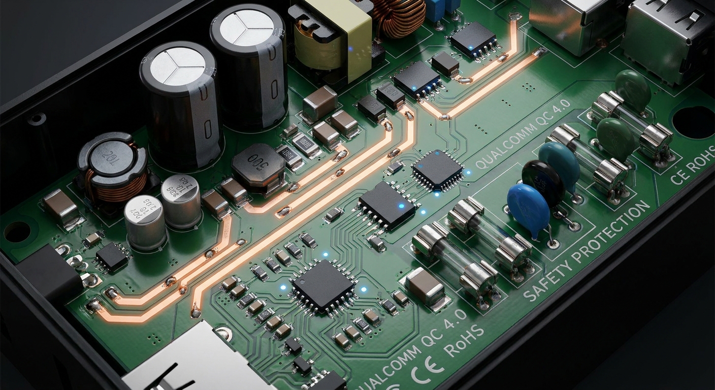
Power adapter protection circuits are integrated safety systems designed to continuously monitor voltage, current, and temperature parameters to prevent damage to downstream components. These robust power adapter protection circuits act as an active buffer shield between the unstable alternating current grid and your valuable electronic devices. By dynamically throttling or cutting power during anomalies, they ensure long-term hardware reliability.
Modern electronic equipment relies heavily on clean and steady direct current to perform complex processing tasks without experiencing operational glitches. Without these safeguards, the slightest ripple in grid stability could easily compromise your hardware’s lifespan. Implementing reliable protection loops protects both your engineering investments and your brand’s market reputation.
How do protective circuits establish safety thresholds?
Think about it: how does an adapter know when a voltage or current spike has crossed the line from normal to hazardous? Integrated comparator circuits continuously match real-time operating metrics against pre-set reference levels.
Here is the key: once a threshold is breached, the controller instantly triggers a shutdown sequence to prevent energy propagation.
- Voltage Sensing: Detects spikes beyond safe tolerance levels.
- Current Monitoring: Prevents excess heat generation by limiting draw.
- Dynamic Response: Executes mitigation tasks within microseconds.
What is the primary difference in circuit architectures?
The reality? Protection designs vary wildly depending on whether they are engineered for consumer, industrial, or medical applications. You will find that simple adapters rely on basic passive components, whereas high-reliability systems integrate complex active ICs.
But that is not all. Active architectures monitor multiple fault conditions simultaneously and offer automatic recovery features that minimize manual service interventions.
- Passive Protection: Low-cost, single-use elements like standard glass fuses.
- Active Protection: Self-healing smart loops managed by intelligent microcontrollers.
- Hybrid Systems: Combined approaches that pair speed with ultimate safety redundancy.
Key Takeaway: Selecting the appropriate circuit architecture ensures your equipment receives the exact level of protection needed for its specific deployment environment, driving down total operational failure rates.
| System Type | Active IC | Passive Elements | |
|---|---|---|---|
| Trigger Speed | Microseconds | Milliseconds | |
| Reusability | Fully Automatic Reset | Manual Replacement Required | |
| Customization | Programmed Thresholds | Fixed Material Thresholds |
Understanding these architectural baselines allows us to examine the critical safety consequences of deploying unprotected adapters.
Why Are Power Adapter Protection Circuits Vital for Safety?
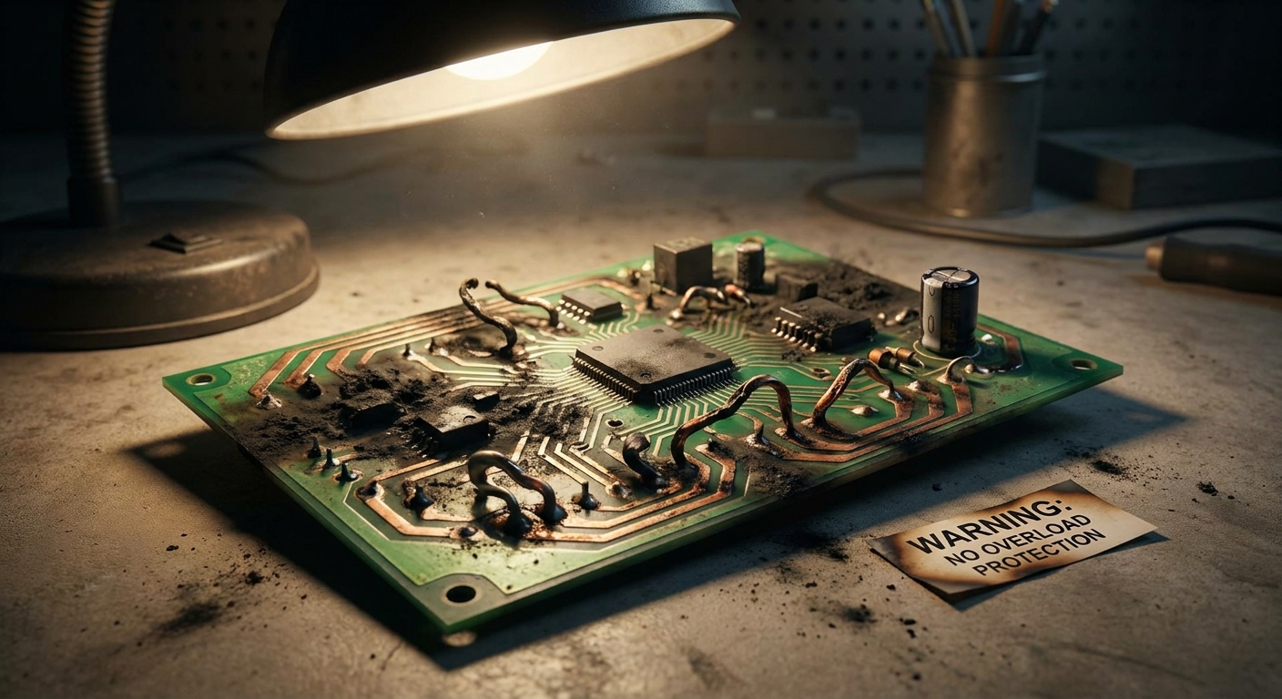
Power adapter protection circuits are vital for safety because they prevent severe electrical faults from translating into destructive thermal runaways, structural fires, or lethal user shocks. Standardizing on certified power adapter protection circuits is a non-negotiable requirement when deploying high-performing electronics in high-stress consumer or industrial environments. These systems act as the primary defense line, ensuring that internal component failures do not escape the adapter’s physical enclosure.
Under normal conditions, an adapter seamlessly steps down grid voltage to a safe, low-level output. However, any structural breakdown within the transformer can bridge primary AC and secondary DC lines, creating immense hazard vectors. Reliable design practices mitigate these threats before they can impact your users or devices.
How do safety circuits prevent electrical fires?
Let’s face it: electrical fire is the absolute worst-case scenario for any hardware manufacturer. When raw electrical energy is uncontrolled, trace elements on a circuit board can reach melting points in seconds.
Here is the key: flame-retardant enclosures must be paired with immediate electrical cutoffs to starve the fault of energy.
- Thermal Cutoffs: Break the circuit when internal temperatures exceed safe limits.
- Overcurrent Tripping: Stops copper traces from acting like heating coils.
- V-0 Flammability Housing: Restricts fire from escaping the adapter shell.
Do safety protections help you gain market access?
Think about it: how will you clear the strict regulatory hurdles imposed by global safety compliance agencies? You cannot legally sell or distribute your equipment in regions like North America or the EU without demonstrating compliance with safety standards.
But that is not all. Utilizing adapters with integrated, pre-certified protection loops accelerates your certification pipeline while reducing custom testing overhead.
- UL Certification: Essential for entry into North American commercial markets.
- CE Mark: Mandated for safety and electromagnetic compatibility in Europe.
- CB Scheme: Simplifies national certification transfers across dozens of member states.
Key Takeaway: Incorporating comprehensive safety circuits protects your end-users from harm while paving a rapid, frictionless path through global compliance frameworks.
| Hazard Class | Mitigation Component | Regulatory Focus | |
|---|---|---|---|
| Electrical Shock | Galvanic Isolation | IEC 62368-1 Safety | |
| Enclosure Fire | V-0 Rated Plastics | UL 94 Standards | |
| Internal Meltdown | Thermal Fuse (OTP) | Global Thermal Compliance |
Now that we recognize the safety imperatives, let us explore how these circuits protect against overcurrent hazards.
How Do Power Adapter Protection Circuits Stop Overcurrent?
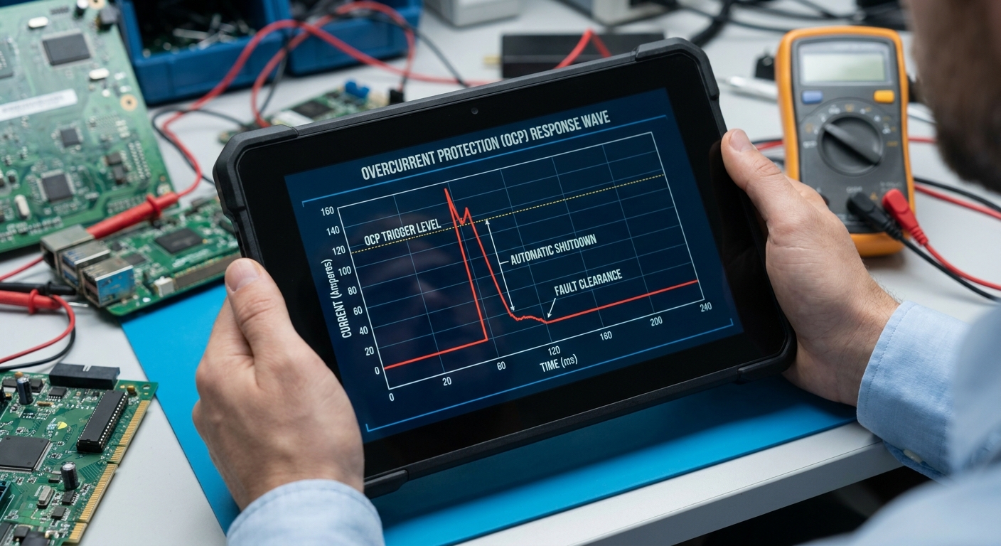
Power adapter protection circuits stop overcurrent by utilizing precise current-sensing resistors and feedback loops that actively throttle or terminate power delivery when current limits are exceeded. When your connected devices demand more current than the system can safely deliver, high-integrity power adapter protection circuits intervene to prevent component overheating. Without this immediate throttling action, the power supply would quickly suffer from copper trace failures and permanent silicon degradation.
Current spikes are common during startup sequences or sudden system workloads, meaning protection loops must differentiate between transient spikes and hard faults. Balancing sensitivity with system reliability is the mark of an expertly engineered adapter. By implementing smart current-sensing networks, you preserve system longevity across all operating states.
What is the mechanics of Overcurrent Protection (OCP)?
The reality? OCP acts as a precise electronic throttle that continuously monitors current draw directly at the secondary output stage. If your device suffers an internal component short and tries to draw massive current, the sensing resistor instantly signals the controller.
Here is the key: the controller limits the output pulse width, lowering the current back to a safe level.
- Sensing Resistors: Provide highly accurate real-time current measurements.
- Control ICs: Actively process sensing data and adjust the switching duty cycle.
- Fast-acting Switches: Interrupt the primary energy flow within microseconds.
What is Hiccup Mode during an overcurrent event?
Think about it: what happens when a temporary overcurrent occurs, and you do not want to manually reset the system? Hiccup Mode is a highly efficient protection mechanism that periodically turns the output power off and on to check if the fault has cleared.
But that is not all. Because the power is only active for brief fractions of a second during “hiccups,” the adapter generates virtually zero heat while waiting for the fault to clear.
- Auto-Restart Cycles: Periodically attempts to restore standard power safely.
- Low Duty Cycle: Keeps thermal energy dissipation at absolute minimums.
- Self-Healing Recovery: Resumes normal operations without operator intervention.
Key Takeaway: Overcurrent protection keeps your hardware safe from excessive current draws, reducing field downtime and eliminating manual resetting overhead.
| OCP Scheme | Response Action | Best Application | |
|---|---|---|---|
| Constant Current | Limits current to max rating | Battery Charging Units | |
| Hiccup Mode | Cycles power off and on | Industrial Machinery | |
| Latch-Off | Shuts down until manual reset | Sensitive Microcontrollers |
Moving past current-related issues, we must analyze how these adapters handle the hazards of overvoltage spikes.
How Do Power Adapter Protection Circuits Prevent Overvoltage?
Power adapter protection circuits prevent overvoltage by utilizing clamping components, optocoupler feedback loops, and high-speed comparator circuits that clamp voltage spikes or shut down the primary converter. Incorporating reliable power adapter protection circuits is essential because your downstream processors operate within incredibly tight voltage tolerances, typically under five percent. If a power surge breaches this threshold, the delicate gates inside your microchips will experience immediate electrical breakdown.
Grid-side surges from lightning strikes or heavy machinery switching can easily feed destructive overvoltage spikes into your device. To mitigate this, protection loops must deploy rapid clampers that absorb this excess energy instantly. Selecting a robust adapter containing these defensive loops protects your equipment from the most common utility grid anomalies.
What are the primary mechanisms of Overvoltage Protection (OVP)?
Look: OVP serves as an absolute hard limit on output voltage to prevent it from ever exceeding safe operating bounds. If the primary regulation loop fails, an independent secondary circuit monitors the output and acts as a mechanical failsafe.
Here is the key: this secondary loop uses an optocoupler to send an isolated shutdown signal directly to the primary controller.
- Zener Diodes: Establish absolute voltage reference thresholds for clamping.
- Optocoupler Feedback: Safely bridges isolation gaps to trigger primary shutdowns.
- Crowbar Circuits: Short-circuit the output rail to deliberately trigger a fuse during extreme faults.
How do TVS diodes absorb transient voltage spikes?
But that is not all. For extremely rapid, high-energy voltage transients, standard feedback loops are simply too slow to react. You must deploy Transient Voltage Suppression (TVS) diodes directly across the input and output lines.
The reality? These specialized semiconductor devices transition from high impedance to near-zero resistance in picoseconds to safely shunt the transient spike away from your device.
- Picosecond Response: Intercepts fast-rising lightning surges instantly.
- High Energy Absorption: Safely dissipates large voltage spikes as harmless heat.
- Parallel Orientation: Protects downstream lines without affecting standard operation.
Key Takeaway: Comprehensive overvoltage protection guarantees that your voltage-sensitive microprocessors remain fully protected from catastrophic grid surges and internal transformer failures.
| OVP Component | Clamping Speed | Maximum Energy | Degradation Over Time | |
|---|---|---|---|---|
| TVS Diode | Picoseconds | Moderate | None (highly reusable) | |
| Zener Diode | Nanoseconds | Low | Minimal | |
| MOV Varistor | Nanoseconds | Extremely High | High (degrades on heavy hits) |
Next, we will explore the high-speed dynamics required to handle immediate short circuits.
How Do Power Adapter Protection Circuits Handle Short Circuits?
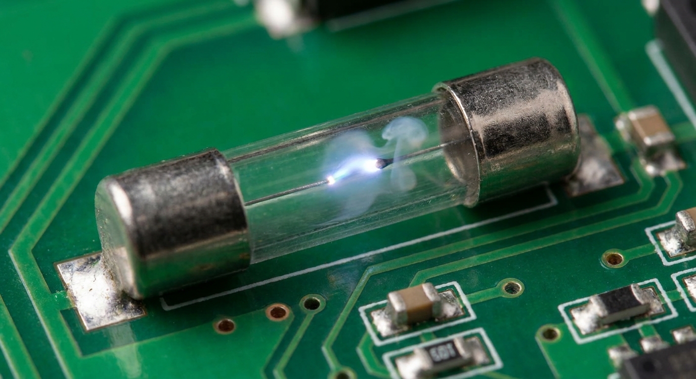
Power adapter protection circuits handle short circuits by detecting sudden, extreme resistance drops and immediately shutting off the switching transistor within microseconds to stop the flow of destructive current. Utilizing highly responsive power adapter protection circuits prevents immediate circuit meltdowns and fire hazards during direct electrical shorts. A short circuit represents the most severe electrical fault, as it removes almost all loop resistance, causing current to rise to near-infinite levels.
Without rapid-acting protection, a short circuit will instantly melt your device’s PCB copper traces and destroy internal power transistors. Standardizing on high-quality adapters guarantees that your systems remain shielded from these catastrophic short-circuit failures. This rapid isolation keeps both the power adapter and your connected electronics completely safe.
How does Short Circuit Protection (SCP) trigger so quickly?
Think about it: a short circuit can cause catastrophic system failure in a matter of milliseconds. SCP loops bypass standard current-monitoring delays and utilize high-speed comparator circuits to identify the massive drop in output impedance.
Here is the key: once a threshold is crossed, the controller disables the main power MOSFET within microseconds.
- Instant Comparator Trip: Bypasses slow filtering components during direct shorts.
- MOSFET Disabling: Cuts off power generation at the primary switching stage.
- Isolated Fault Containment: Ensures the short circuit does not propagate through the system.
What are the benefits of auto-recovery during short circuits?
The reality? If your field technician makes a minor wiring mistake, you do not want to replace the entire power supply. An SCP loop with auto-recovery will safely keep the output disabled while the short is active.
But that is not all. Once the physical short is removed, the adapter automatically detects the restored resistance and resumes standard power delivery.
- No Blown Fuses: Saves you from expensive maintenance and replacement costs.
- Continuous System Uptime: Restores system operation immediately after fault clearance.
- Safe Line Testing: Employs low-power pulses to safely check the line status.
Key Takeaway: Implementing SCP with smart auto-recovery prevents catastrophic PCB damage and completely eliminates costly field maintenance calls.
| Short Circuit Type | Detection Window | Adapter Response | Recovery Mode | |
|---|---|---|---|---|
| Direct Hard Short | < 10 microseconds | Absolute Cutoff | Hiccup / Auto-recovery | |
| High-Impedance Short | < 100 microseconds | Current Throttling | Normalizes on Load Drop | |
| Intermittent Short | Variable | Fast Shutdown | Periodic Line Sensing |
Now that we understand short-circuit isolation, let us examine how thermal protection circuits prevent overheating.
How Do Power Adapter Protection Circuits Prevent Overheating?
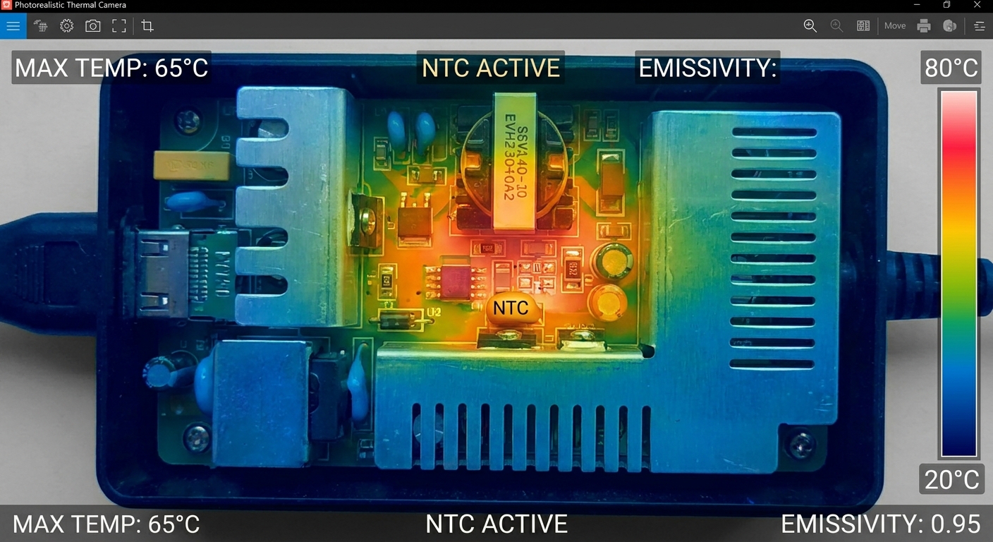
Power adapter protection circuits prevent overheating by utilizing negative temperature coefficient (NTC) thermistors to monitor thermal states and shut down power output when temperatures exceed safe thresholds. In closed, poorly ventilated environments, choosing adapters with intelligent power adapter protection circuits prevents thermal runaway and component melting. High heat degrades electrolytic capacitors and other critical silicon parts, leading to premature aging and unpredictable system failures.
By integrating thermal protection loops, adapters can handle extreme environmental temperatures without risking fires or board damage. These safeguards ensure your hardware operates strictly within safe thermal envelopes. Thermal safety is particularly crucial for compact power supplies deployed in industrial or confined commercial enclosures.
What is the mechanism behind Over Temperature Protection (OTP)?
Think about it: how does a sealed plastic adapter box protect itself from internal heat buildup? OTP systems rely on strategically placed NTC thermistors soldered directly onto the PCB, right next to the hot switching components.
Here is the key: as the temperature rises, the thermistor’s electrical resistance drops, signaling the controller to shut down before damage occurs.
- Continuous Thermal Tracking: Monitors localized heat spikes near transformers and MOSFETs.
- Thermal Shutdown Threshold: Automatically cuts power when temperatures exceed safety limits (typically 120°C–130°C).
- Hysteresis Reset: Prevents the unit from cycling back on until it has cooled to safe levels.
Why is thermal management critical in compact power adapters?
Let’s face it: today’s high-power, compact wall adapters have very little surface area to dissipate thermal energy. You must have active OTP to prevent localized hot spots from damaging the outer plastic casing.
But that is not all. Superior adapter designs combine active OTP with advanced heat-spreading potting compounds and aluminum heat sinks.
- Thermal Potting: Conducts heat away from hot spots to eliminate localized heat stress.
- Integrated Heat Sinks: Increases surface area to maximize natural convective cooling.
- High-Efficiency Topology: Lowers initial waste heat generation by optimizing power conversion.
Key Takeaway: Over-temperature protection safeguards your investment from thermal degradation, maintaining structural safety and extending product lifespans.
| Enclosure Grade | Max Operating Temp | Thermal Safety Action | Cooling Method | |
|---|---|---|---|---|
| Standard Commercial | 45°C Ambient | Latch-off at 115°C PCB Temp | Convective Heat Sinks | |
| Medical Grade | 40°C Ambient | Strict Shutdown at 90°C | Potting Compound | |
| Rugged Industrial | 70°C Ambient | Hiccup Thermal Recovery | Extended Metal Housings |
Let us next identify the primary electronic components that make these protective loops possible.
What Components Are in Power Adapter Protection Circuits?
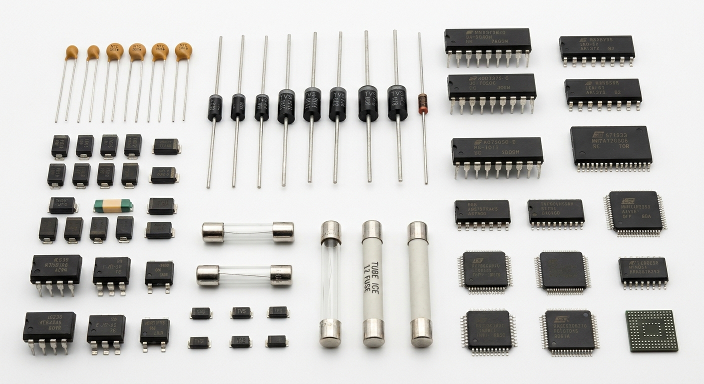
Power adapter protection circuits consist of a carefully engineered combination of fuses, metal oxide varistors, transient voltage suppressors, NTC thermistors, and active monitoring ICs working in harmony. Selecting power supplies featuring high-grade components within their power adapter protection circuits ensures rapid response times and long-term durability. Each component is chosen for its specific response characteristics to provide defense-in-depth protection.
From the moment raw AC power enters the adapter to the millisecond clean DC voltage leaves it, multiple component stages guard the loop. A failure in even one cheap component can bypass safety layers, highlighting the importance of premium component sourcing. Sourcing from certified manufacturers ensures your protection components perform exactly when needed.
What are the roles of primary input protection components?
Think about it: the primary side of the adapter faces the direct brunt of grid-side lightning strikes and utility spikes. You must have rugged component boundaries like Metal Oxide Varistors (MOVs) and ceramic fuses to block these surges right at the entrance.
Here is the key: these parts absorb high-energy spikes before they can compromise the sensitive primary-side transformer windings.
- Ceramic Fuses: Physically break the line during extreme, catastrophic overcurrent events.
- Metal Oxide Varistors: Clamp high-voltage surges coming from the AC grid.
- NTC Thermistors: Restrict high startup inrush current when plugging into an outlet.
How do secondary-side components ensure safe output delivery?
But that is not all. Once power crosses the isolation transformer, you need secondary-side components to fine-tune protection parameters and keep voltages clean. Optocouplers provide isolated signal feedback across the high-voltage boundary without any physical wire connections.
The reality? This optical isolation keeps your users completely safe from receiving high-voltage shocks from the AC primary side.
- Optocouplers: Use light waves to transmit safety and regulation signals.
- Secondary TVS Diodes: Provide final, high-speed voltage clamping on the DC output rail.
- Shunt Regulators: Work with feedback loops to maintain highly stable voltage outputs.
Key Takeaway: Sourcing adapters built with rugged, high-quality components ensures your protective circuits respond reliably to electrical faults, preventing downstream failure cascades.
| Component Class | Board Placement | Operational Life | Primary Task | |
|---|---|---|---|---|
| Ceramic Fuse | AC Primary Inlet | Single-use Fault Break | Stops catastrophic current | |
| MOV Varistor | Across AC Lines | Finite (degrades on hits) | Clamps grid voltage surges | |
| Optocoupler | Isolation Barrier | Permanent (highly stable) | Galvanic feedback isolation |
Sourcing the right components is only half the battle; we must now examine how these safety systems are verified in the lab.
How Are Power Adapter Protection Circuits Tested and Verified?
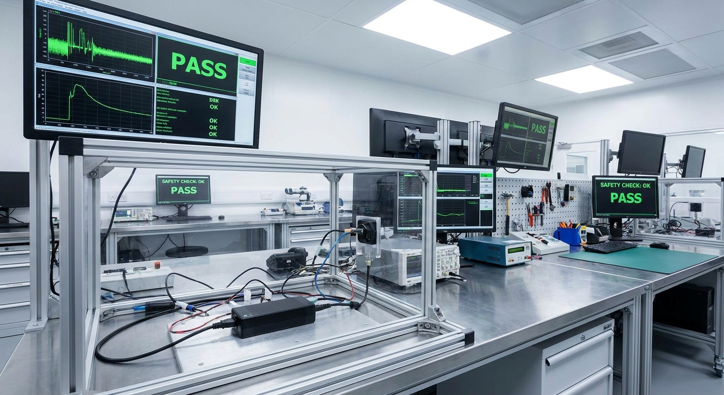
Power adapter protection circuits are tested and verified using automated electronic loads, environmental chambers, high-voltage generators, and thermal scanners to simulate harsh field faults. Thorough testing of your power adapter protection circuits ensures that safety systems activate at precise electrical limits and recover predictably under load. This exhaustive process prevents premature field failures and protects your brand from costly recalls or liability claims.
Lab testing is critical because theoretical circuit designs must be proven in physical, harsh operating conditions. Quality manufacturers subject every production run to strict testing phases before shipment. This thorough quality control methodology maintains batch-to-batch consistency and high operational uptime.
What are the primary electrical test protocols?
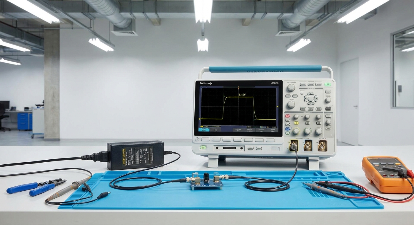
Look: you cannot verify microseconds-fast protection loops with standard multimeters. Technicians use high-speed programmable electronic loads to ramp current levels and measure the exact microsecond OCP trip points.
Here is the key: oscilloscopes capture these high-speed waveforms to verify that voltage clamps activate before downstream devices suffer damage.
- Short Circuit Simulation: Tests that SCP activates and safely transitions to Hiccup mode in under 10 microseconds.
- Overvoltage Clamping Test: Verifies TVS diodes successfully clamp fast-rising voltage spikes.
- Dielectric Strength Testing: Subjects isolation barriers to thousands of volts to guarantee safety compliance.
What do environmental stress and burn-in tests achieve?
But that is not all. To ensure component safety margins do not drift over years of use, power supplies undergo prolonged burn-in tests. You will find that running units under full load in heated chambers reveals weak components before they leave the factory floor.
The reality? A rigorous 100% full-load burn-in process reduces field failure rates to negligible fractions of a percent.
- Full-Load Aging: Simulates weeks of continuous operational stress within a 4-hour window.
- Thermal Chamber Cycling: Tests protection performance across extreme cold and hot temperatures.
- High-Humidity Testing: Verifies that internal circuits resist moisture-related tracking and leakage currents.
Key Takeaway: Strict lab verification protocols guarantee that your power supplies perform flawlessly when critical electrical faults occur in real-world applications.
| Verification Test | Equipment Used | Target Standard | Primary Quality Objective | |
|---|---|---|---|---|
| Dielectric Hipot | High-Voltage Tester | > 3000V AC Isolation | Eliminates shock risks | |
| Current Load Ramp | Programmable Load | Exact Current Threshold | Confirms overcurrent limits | |
| Burn-in Aging | Heated Chamber | 4-Hour Test Cycle | Weed out early component defects |
Now, let us examine the extreme operational risks you face if you bypass these essential protective systems.
What Happens Without Power Adapter Protection Circuits?
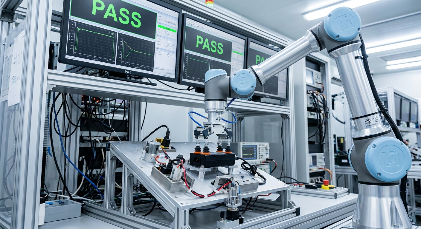
Without power adapter protection circuits, any minor voltage spike, short circuit, or thermal anomaly will transfer directly into your connected hardware, resulting in instant device meltdowns, data corruption, or severe fires. Deploying high-integrity power adapter protection circuits is the only way to avoid catastrophic failures and ensure product reliability. Unprotected power supplies lack the vital barriers needed to isolate dangerous high-voltage spikes and currents.
Sourcing cheap, non-certified adapters to save pennies frequently results in astronomical warranty costs and irreversible damage to your company’s market reputation. When an unprotected adapter suffers an internal failure, it frequently destroys the valuable equipment it powers. Standardizing on high-integrity adapters is the best way to safeguard your hardware investments.
What are the catastrophic risks of unshielded adapters?
Think about it: what happens when an unprotected adapter encounters an AC grid surge? Because there are no clamping diodes or feedback loops to intercept the surge, thousands of volts surge straight into your device’s motherboard.
Here is the key: this high-voltage surge instantly vaporizes microchip silicon, leading to permanent, unrepairable equipment failure.
- Blown Silicon Gates: Destroys microprocessors and solid-state storage chips.
- Carbonized PCB Boards: Creates high-current paths that can start fires inside enclosures.
- User Shock Hazard: High voltage can bridge the primary-to-secondary gap, shocking operators.
How do field failures increase your operating costs?
The reality? The true cost of using cheap, unprotected power supplies goes far beyond the initial unit price. You will face a mountain of customer support tickets, high product return rates, and the massive logistics headache of field recalls.
But that is not all. High failure rates erode customer trust, driving your partners straight to your competitors who prioritize power safety.
- Increased RMA Rates: Drives up overhead costs for processing customer returns.
- Field Service Costs: Demands expensive engineering dispatch times to swap out units.
- Brand Reputation Loss: Negative reviews and broken trust can permanently damage your business.
Key Takeaway: Skimping on power protection leads to immediate device vulnerabilities, higher operational failure rates, and long-term damage to your brand.
| Power Supply Type | Field Failure Rate | Average Lifespan | Impact on Brand Reputation | |
|---|---|---|---|---|
| Unprotected Adapter | 2.1% or higher | < 12 Months | High risk of safety recalls | |
| Protected Adapter | < 0.02% | 5+ Years | Strong customer retention | |
| Medical Grade Adapter | < 0.01% | 7+ Years | Unmatched regulatory trust |
Let us finally learn how to optimize these protection systems to achieve maximum operational reliability.
How to Enhance Power Adapter Protection Circuits’ Reliability?

To enhance power adapter protection circuits’ reliability, you must implement component derating, optimize PCB creepage distances, and integrate advanced multi-stage safety controller ICs. Designing robust power adapter protection circuits requires selecting components rated for voltage and thermal loads well beyond their expected operating maximums. This strategy provides a vital buffer that prevents early component fatigue and keeps systems running during unexpected surges.
Additionally, maintaining clear physical isolation between primary high-voltage and secondary low-voltage rails on the PCB prevents high-voltage electrical arcing. By combining proper layout geometry with high-grade components, you maximize protection speeds and product longevity. Advanced design principles are essential to ensure long-term stability in harsh industrial settings.
Why is component derating critical for protection lifespan?
Look: running electronic components close to their absolute thermal or voltage limits leads to rapid degradation and early field failures. Component derating means intentionally selecting parts rated for much higher loads, such as using 50V capacitors on a 24V line.
Here is the key: this extra safety margin dramatically reduces component stress and extends the overall life of the power supply.
- Voltage Margin: Running capacitors and transistors at 80% or less of their maximum voltage ratings.
- Thermal Headroom: Keeping component junction temperatures well below silicon limits.
- Reduced Stress: Extends mean time between failures (MTBF) to tens of thousands of hours.
How does proper PCB layout geometry prevent failure?
Think about it: if your PCB traces are placed too close together, a high-voltage surge can easily arc across the gap, bypassing your protective circuits entirely. You must maintain proper creepage and clearance distances to keep the input and output stages isolated.
But that is not all. High-quality layouts include physically milled isolation slots in the PCB substrate to prevent tracking currents in high-humidity environments.
- Milled Isolation Slots: Physically cuts the circuit board substrate to block high-voltage leakage.
- Wide Copper Traces: Lowers track resistance and prevents hot spots during high current flows.
- Strategic Ground Planes: Reduces electromagnetic interference and improves noise immunity.
Key Takeaway: Optimizing board layout and choosing derated components ensures your power supplies remain stable, reliable, and functional across years of continuous operation.
| Optimization Target | Recommended Engineering Standard | Primary Protection Benefit | |
|---|---|---|---|
| Component Derating | 20% minimum safety headroom | Drastically reduces component fatigue | |
| PCB Creepage Space | > 8.0 mm (Primary to Secondary) | Eliminates high-voltage arc-over risk | |
| Thermal Heat Sinking | Direct copper pour + thermal vias | Maintains low component temperatures |
Having detailed the technical mechanics and optimization paths, let us wrap up with strategic procurement decisions.
Conclusion
Selecting power adapters with robust, certified protection circuits is the single most effective action you can take to shield your high-value hardware from destructive overvoltages, overcurrents, short circuits, and thermal failures. For over two decades, Merryking has served as a premier global manufacturer, delivering highly reliable 1W–600W AC/DC adapters with pre-approved certifications (UL, CE, FCC, CB, UKCA, and more) designed to help you enter global markets seamlessly. Our dual-factory Shenzhen and Dongguan bases provide the stable capacity, rapid prototyping, and custom engineering support needed to tailor power solutions directly to your product’s requirements. We stand firmly behind the quality of every unit we ship, maintaining a strict 3-stage quality control process to guarantee batch-to-batch consistency. Protect your hardware investments and eliminate supply chain uncertainty— contact us today to discuss your custom OEM requirements or request a rapid sample.
Frequently Asked Questions
Can I use a power adapter without safety certifications for test-phase prototypes?
Yes, you can, but only in controlled lab environments with continuous professional monitoring. Using uncertified adapters in any customer-facing pilot or commercial release is highly risky and can lead to severe equipment damage, liability issues, and regulatory fines.
What’s the best way to verify if my power adapter has active short circuit protection?
Check the official product datasheet or laboratory test report for ‘SCP with Auto-Recovery’. A reliable adapter will explicitly list a response time under 10 microseconds and confirm a transition to Hiccup mode or complete latch-off during short-circuit faults.
How do I know if an adapter has true over temperature protection?
Look for safety certification markings (like UL or GS) and verified NTC thermistor listings on the internal bill of materials (BOM). True over temperature protection will actively shut down the power supply output when internal temperatures cross critical thresholds, rather than letting the unit melt.
Can I request customized protection thresholds for my specific industrial hardware?
Yes, you can request custom limits because factory-direct manufacturers like Merryking can fully customize OCP, OVP, and OTP thresholds during the OEM/ODM development stage. This ensures the adapter’s trip-points align perfectly with your hardware’s unique voltage and current tolerances.
What’s the best way to prevent inrush current from damaging my system during start-up?
Choose power adapters built with integrated NTC thermistors or active soft-start circuits on the AC input side. These specialized components temporarily limit the initial surge of current as the bulk capacitors charge, ensuring a smooth, safe start-up every single time.