What Is Power Cord Voltage Drop?
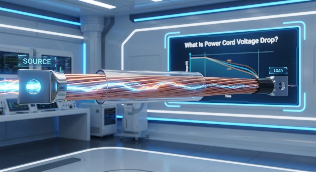
Power cord voltage drop is the unavoidable reduction in electrical potential that occurs as current travels from a power supply to your connected device. If your expensive hardware experiences sudden reboots or operational instability, a poorly specified cable is often the hidden culprit that compromises your entire system. This electrical bottleneck can lead to hardware failures, thermal hazards, and critical operational downtime in demanding environments. Specifying high-quality cables is the ultimate solution to control power cord voltage drop and ensure your devices receive stable power.
This electrical loss occurs because every physical conductor contains inherent internal resistance that converts a portion of current into heat energy. B2B buyers must prioritize calculating this electrical loss when engineering custom hardware setups or deploying commercial systems. Operating your equipment with a stable voltage level ensures long-term performance and minimizes the risk of safety hazards. By choosing the correct material composition and wire geometry, you can completely eliminate these performance bottlenecks.
How Does Ohm’s Law Apply?
Ohm’s Law states that voltage drop is directly proportional to the current load and the resistance of the conductor. Think about it: any increase in current draw or wire resistance will immediately amplify your electrical losses. To keep your systems running at peak efficiency, you must actively manage these variables. The primary factors that dictate this resistance include conductor purity, overall cross-sectional area, and the temperature of the operating environment.
When designing system setups, you cannot ignore how minor resistance additions multiply over long runs. Here are the key variables that influence this equation:
- Conductor resistivity: The inherent resistance of the copper wire material.
- Current load: The volume of electrical current flowing through the circuit.
- Contact resistance: Resistance introduced at termination points and plug pins.
Is Any Voltage Loss Safe?
Small amounts of electrical drop are completely normal and accounted for in standard electronic device designs. However, when the loss exceeds acceptable safety margins, your hardware reliability will plummet rapidly. Standard designs typically tolerate a minor drop of one to three percent without experiencing any operational glitches. If the loss exceeds five percent, your devices will struggle to operate safely and may suffer permanent damage.
Key Takeaway: Specifying power cables with low internal resistance ensures your systems maintain peak efficiency, preventing expensive hardware failures and reducing downtime.
Why Does Power Cord Voltage Drop Matter in Power Adapter Applications?

Power cord voltage drop matters in power adapter applications because external power adapters must deliver a highly precise, regulated DC voltage to sensitive downstream devices. If the input or output cables experience excessive electrical loss, the device will receive voltage levels below its minimum operational threshold. This gap can cause erratic controller operations, connection drops, or complete hardware shutdowns. Managing power cord voltage drop is essential to maintain product reliability and eliminate costly warranty returns for B2B buyers.
When current flows through a thin adapter cable, the physical resistance converts valuable electrical power into thermal energy. This localized heating not only wastes power but also accelerates the aging of the cable insulation over time. To protect your brand reputation, choosing optimized adapter cables is a vital step in product development. High-quality designs guarantee that your devices operate within their intended electrical parameters.
How Do Adapters Adjust?
Smart power adapters can use active line drop compensation to dynamically boost their output voltage based on current draw. But that is not all: if the adapter does not actively compensate, the voltage at the device plug will sag under heavy workloads. This dynamic adjustment ensures that the connected device receives a perfectly flat voltage curve. Manufacturers often implement this to offset physical line losses without requiring bulky cable upgrades.
These adjustment methods vary depending on the target application requirements and budget constraints. Let’s look at the primary ways manufacturers solve this:
- Active Line Compensation: Dynamically increases voltage output at the source.
- Passive Over-provisioning: Setting the nominal voltage slightly higher (e.g., 5.1V).
- Thicker Output Conductors: Directly lowering physical resistance to prevent losses.
What Are the Thermal Risks?
Excessive electrical resistance in adapter cables does not just cause voltage sag; it directly generates localized heat. This thermal buildup can severely degrade the cable jacket, increasing the risk of short circuits. In enclosed industrial cabinets, this heat accumulation can lead to system-wide thermal issues and early component fatigue. Ensuring proper thermal dissipation is crucial for the safety and longevity of your equipment.
Key Takeaway: Choosing adapters with active line compensation or upgraded wire gauges ensures your sensitive electronic devices receive stable voltage while minimizing unsafe thermal buildup.
| Compensation Method | Output Stability | Thermal Output | Cost Impact | |
|---|---|---|---|---|
| No Compensation | Poor (drops under load) | Low (in adapter) | Low | |
| Passive (Over-provisioning) | Moderate | Low | Low | |
| Active Line Compensation | Excellent | Medium | Moderate | |
| Upsized Wire Gauge | Excellent | Very Low | Moderate to High |
Evaluating these compensation techniques helps engineering teams balance manufacturing costs against the thermal and operational demands of their hardware systems.
What Causes Power Cord Voltage Drop in Electrical Systems?
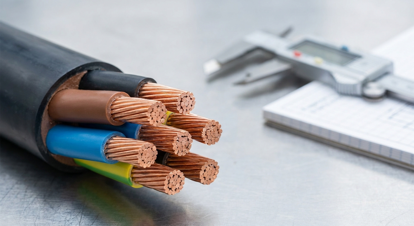
Power cord voltage drop in electrical systems is caused by the physical resistance of the conductor, the length of the run, and the current load. When current flows, electrons collide with the internal atoms of the metal, transforming electrical energy into heat. Understanding these underlying physical drivers allows B2B engineers to prevent excessive power cord voltage drop from disrupting industrial operations. Managing these environmental and material factors is the first step toward building a highly reliable power distribution network.
Poor material quality and worn mechanical connections also introduce major resistive barriers in a power path. Over time, exposure to moisture and oxygen can cause electrical contacts to degrade and oxidize rapidly. This degradation creates high-resistance contact points that amplify energy losses across the entire assembly. Selecting robust, industrial-grade components is vital for eliminating these avoidable performance bottlenecks.
Why Does Material Choice Matter?
The purity and type of metal used inside your power cables directly dictate their electrical resistance. Let’s face it: choosing cheap conductor materials to save upfront manufacturing costs always leads to systemic failure downstream. Pure copper offers superior conductivity and durability, whereas cheap alternatives introduce massive resistance penalties. Protecting your equipment starts with ensuring your supplier utilizes high-grade, premium materials.
Different conductor materials exhibit vastly different electrical characteristics under sustained loads. Consider these common options:
- Oxygen-Free Copper (OFC): Provides the highest conductivity and maximum durability.
- Bare Copper (BC): Serves as the standard commercial-grade conductor.
- Copper-Clad Aluminum (CCA): Introduces high resistance and mechanical fragility.
How Do Terminals Degrade?
The physical connection between the plug pins and the device socket introduces contact resistance. Over time, environmental oxidation and repeated insertions can wear down these critical mating surfaces. This physical wear creates a bottleneck that increases the overall energy loss of the assembly. Regular maintenance and high-quality plating are required to keep these connections performing efficiently.
Key Takeaway: Specifying 100% pure copper conductors and high-quality plated contacts is the most effective way to eliminate unexpected resistance-related voltage drops.
| Material Type | Resistivity (μΩ⋅cm) | Relative Conductivity (%) | Recommended Application | |
|---|---|---|---|---|
| Oxygen-Free Copper | 1.68 | 100% | High-reliability industrial & medical cords. | |
| Bare Copper | 1.72 | 97.6% | Standard consumer power supplies. | |
| Aluminum | 2.65 | 63.4% | Not recommended for flexible power cords. | |
| Nickel-Plated Brass | 7.00 | 24% | Heavy-duty electrical connector pins. |
By analyzing material resistivity profiles, engineers can select the most efficient metals to prevent operational degradation in demanding environments.
How Do Cable Length and Wire Gauge Affect Power Cord Voltage Drop?
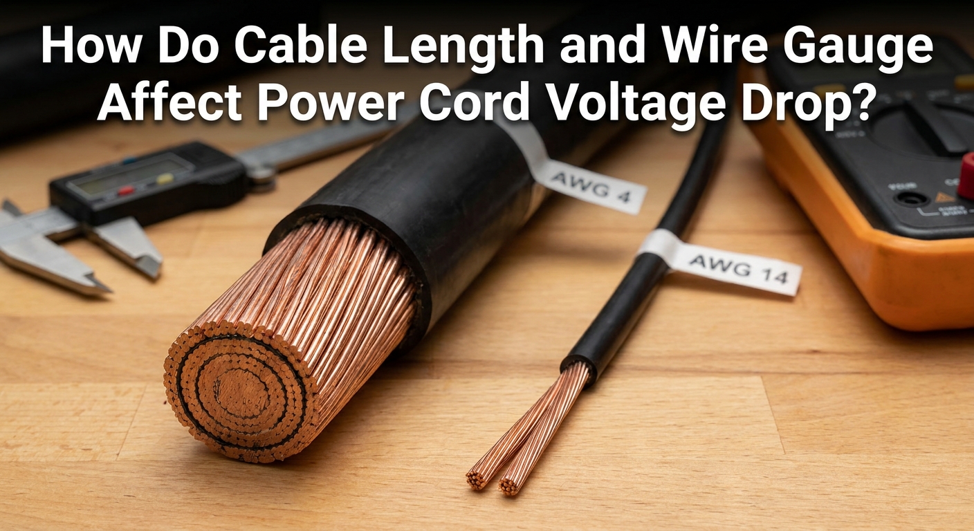
Cable length and wire gauge affect power cord voltage drop in a mathematically linear relationship where longer cables and thinner wires exponentially increase overall circuit resistance. A longer physical path forces current to traverse more resistive material, compounding energy losses. Conversely, a thicker wire gauge provides a larger cross-sectional area that reduces physical resistance and lowers overall power cord voltage drop. Balancing these physical dimensions is critical to delivering safe and efficient power to your devices.
Understanding this dimensional relationship allows you to optimize your cable architecture during the design phase. Engineering teams must avoid over-specifying cable lengths while selecting appropriate wire gauges to maintain electrical efficiency. This careful balancing act prevents voltage sagging and keeps thermal output to a minimum. Ultimately, proactive design choices lead to highly reliable power setups that perform flawlessly under load.
Why Does Distance Matter?
When routing power over extended distances, cable length acts as a linear multiplier for total circuit resistance. Think about it: a ten-meter cord will exhibit exactly twice the resistance of an identical five-meter cord. This means your voltage losses will double unless you actively compensate by adjusting the wire gauge. Keeping cable runs as short as possible is a fundamental rule in high-efficiency design.
To manage distance-related electrical losses, engineers categorize cable lengths into clear application groups. Consider these standard classifications:
- Short-run cords (under 1.5m): Minimal impact, allowing thinner gauges.
- Medium-run cords (1.5m to 3m): Standard lengths requiring optimized gauge selection.
- Long-run cords (over 3m): High-risk runs requiring upsized wire gauges.
How Does AWG Size Work?
The American Wire Gauge system is logarithmic and runs in reverse, meaning smaller numbers designate thicker conductors. Upgrading to a thicker wire size provides more cross-sectional area, which instantly lowers the conductor’s resistance. For high-draw equipment, choosing a larger wire size is the most reliable way to stabilize incoming voltage. This simple hardware adjustment prevents the performance glitches associated with electrical sagging.
Key Takeaway: To maintain system stability over long distances, you must decrease the AWG number to offset the resistance added by the physical length.
| AWG Rating | Conductor Diameter (mm) | Resistance (Ω/km) | Max Recommended Current (A) | |
|---|---|---|---|---|
| 24 AWG | 0.511 | 84.2 | 1.0A | |
| 22 AWG | 0.644 | 52.9 | 1.5A | |
| 20 AWG | 0.812 | 33.3 | 2.5A | |
| 18 AWG | 1.024 | 20.9 | 5.0A | |
| 16 AWG | 1.291 | 13.2 | 8.0A |
Comparing these AWG physical properties highlights how upsizing wire thickness by just a few steps can drastically improve current-carrying capacity and efficiency.
How Can Excessive Power Cord Voltage Drop Impact Device Performance?

Excessive power cord voltage drop impacts device performance by causing erratic operations, spontaneous system reboots, and accelerated hardware degradation. Microprocessors and sensitive control circuits require a highly stable voltage window to execute operations reliably without crashing. If the incoming power sags below this threshold, you risk triggering unpredictable system behaviors or permanent component damage. Minimizing power cord voltage drop is therefore non-negotiable for critical enterprise and industrial setups.
When devices do not receive their required electrical potential, their internal switch-mode regulators must work significantly harder. This forced compensation increases internal operating temperatures, which severely reduces the lifetime of your hardware. B2B operators must address these undervoltage issues to maintain consistent uptime and prevent premature system failures. Proactive cable management is key to ensuring continuous, reliable hardware operation in the field.
Why Do Devices Reboot?
During initial startup, equipment often draws a high current surge to power up internal fans, transmitters, or drives. Why does this matter? This sudden surge increases the voltage loss along the cable, dipping input levels below the device’s low-voltage lockout threshold. This electrical dip forces the system into an infinite loop of reboots and crashes. The hardware will appear to idle perfectly but will immediately fail under active operating loads.
This unstable boot behavior can disrupt critical workflows and lead to severe data corruption. To prevent this, you should ensure your power cables are rated for peak currents rather than average loads. Here are typical symptoms of poor power delivery:
- Spontaneous resetting: Triggered by transient current spikes.
- Screen flickering: Caused by voltage instability in the display backlight.
- Wi-Fi dropouts: Undervoltage affecting transceiver output power.
How Are Parts Stressed?
When input voltage drops, internal DC-DC converters must draw additional current to maintain their output wattage. This increased current flow generates intense heat within the device’s internal power management units. Over time, this constant thermal stress accelerates component aging and leads to premature hardware breakdowns. Using properly rated power cables protects these sensitive internal parts from thermal overload.
Key Takeaway: Eliminating excessive voltage drop ensures consistent current delivery during peak surges, preventing boot loops and safeguarding expensive internal components.
| Component Type | Minimum Operating Window | Primary Failure Mode | Severity | |
|---|---|---|---|---|
| DC-DC Converter | ± 10% | Thermal overload due to high current | High | |
| Wi-Fi Transceiver | ± 5% | Constant packet loss and disconnections | Medium | |
| Solenoid Valve | ± 15% | Failure to actuate / weak holding force | High | |
| Hard Disk Drive | ± 5% | Data corruption / spindle motor stall | Critical |
Reviewing these component operating windows illustrates why maintaining tight voltage tolerances is critical for avoiding catastrophic hardware failures.
How Is Power Cord Voltage Drop Calculated?

Power cord voltage drop is calculated using a standard formula derived from Ohm’s Law:
Vdrop=I×R×L
, where
I
is the load current in Amperes,
R
is the conductor resistance, and
L
is the total length of the power path. For standard two-wire DC cables, you must double the physical length in your calculations because current must travel to the device and return to the source. Accurately determining your expected power cord voltage drop during the early engineering phase prevents costly redesigns. Taking time to run these calculations ensures your power architecture meets all operational criteria.
Using standardized conductor resistance tables allows you to easily estimate losses across different wire sizes. Failing to calculate these losses accurately can result in under-specified hardware that fails in the field. B2B designers must perform these checks to guarantee that connected equipment receives its minimum required voltage. This analytical approach forms the foundation of reliable product development.
What Formulas Apply?
Single-phase AC systems require calculating impedance, which includes both resistance and reactance, whereas DC systems rely solely on pure conductor resistance. Let’s face it: many engineering teams mistakenly use single-conductor calculations for DC cords, forgetting that current must travel down and back. This common oversight effectively halves the calculated resistance, leading to unexpected performance issues. Using the correct formula for your specific power system is essential for accurate results.
The specific mathematical equations vary depending on the electrical system configuration. Make sure to apply the appropriate calculation for your setup:
- DC Voltage Drop Formula: Vdrop=2×I×R×L (for 2-wire cables).
- AC Single-Phase Formula: Vdrop=2×I×(Rcosθ+Xsinθ)×L.
- AC Three-Phase Formula: Vdrop=3×I×(Rcosθ+Xsinθ)×L.
How Can You Estimate?
Engineers can utilize standardized copper resistance charts alongside online calculator tools to quickly estimate voltage drops across different AWG sizes. By entering the maximum peak current, the exact length, and the operating temperature, you can map out a highly reliable safe-operating zone. This quick evaluation helps you identify potential power issues before ordering raw production materials. Making this a standard part of your workflow ensures robust system performance.
Key Takeaway: Always use the two-way loop resistance formula (
2×I×R×L
) when calculating DC cable drops to avoid underestimating the actual voltage loss.
| Cable Length (m) | Wire Gauge (AWG) | Estimated Resistance (Ω) | Calculated Voltage Drop (V) | Percentage Loss (%) | |
|---|---|---|---|---|---|
| 3.0m | 24 AWG | 0.505 | 1.51V | 12.5% (Unacceptable) | |
| 3.0m | 22 AWG | 0.317 | 0.95V | 7.9% (Marginal) | |
| 3.0m | 20 AWG | 0.200 | 0.60V | 5.0% (Action Required) | |
| 3.0m | 18 AWG | 0.125 | 0.38V | 1.95% (Safe) |
Analyzing these calculated values proves that selecting an appropriate wire gauge is the most direct way to keep voltage losses within safe operational limits.
What Standards and Requirements Apply to Power Cord Voltage Drop?
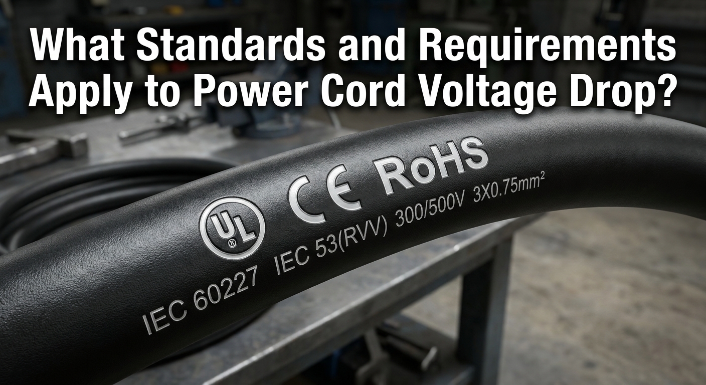
Standards and requirements governing power cord voltage drop are established by international regulatory bodies like UL, IEC, and Energy Star to guarantee safety, operational efficiency, and low energy waste. These global agencies define strict boundaries for acceptable energy losses across commercial and industrial power delivery paths. Compliance with these specifications is required to pass safety audits and secure global market access for your products. Minimizing power cord voltage drop is therefore a fundamental design requirement for passing international certifications.
Failing to meet these safety standards can lead to product recalls, legal liabilities, and compromised customer safety. Designers must ensure that their power solutions strictly adhere to the guidelines set by national electrical codes. This structured compliance protects your company from operational risks and builds trust with enterprise clients. Partnering with a certified manufacturer ensures your designs always meet these stringent global benchmarks.
What Are NEC Limits?
The National Electrical Code recommends a maximum voltage drop of three percent on branch circuits and a maximum combined drop of five percent across both feeder and branch circuits. Think about it: while these guidelines are technically informational in some jurisdictions, major testing laboratories strictly enforce them during device certification. Adhering to these limits prevents hazardous overheating in walls and equipment racks. Keeping your electrical layouts within these boundaries is essential for passing safety inspections.
These regulatory guidelines are designed to protect both users and equipment from electrical failures. Here are the core limits you must monitor:
- Branch Circuit Limit: 3% maximum voltage drop at the farthest outlet.
- Combined Feeder/Branch Limit: 5% total system voltage drop.
- Low Voltage DC Limits: Restricted to 2% to 3% to maintain electronic regulator efficiency.
What Are IEC Rules?
IEC standards, specifically IEC 60364, specify acceptable voltage drop values depending on whether the installation is for lighting, power, or auxiliary services. These international standards ensure that equipment manufactured in one region performs safely and predictably when deployed globally. Meeting these guidelines ensures your product is ready for seamless international distribution. Standardizing your designs around these global parameters reduces your engineering overhead.
Key Takeaway: Designing power cords to meet a 3% or lower voltage drop limit ensures compliance with global safety standards and energy-efficiency certifications.
| Standard Body | Application Area | Max Permissible Drop (%) | Key Focus | |
|---|---|---|---|---|
| NEC (USA) | Branch Circuits | 3% | System efficiency and fire prevention. | |
| IEC 60364 | Power Installations | 4% | Global equipment compatibility. | |
| Energy Star | External Power Supplies | Line-loss dependent | No-load power consumption & active efficiency. | |
| UL 60950/62368 | Information Technology | Product-specific | Operational safety under thermal stress. |
Comparing these regulatory standards demonstrates a global consensus on keeping electrical losses under five percent to ensure safety and system reliability.
How Can Manufacturers Minimize Power Cord Voltage Drop?
Manufacturers can minimize power cord voltage drop by utilizing high-conductivity raw materials, optimizing wire geometry, and engineering active compensation circuits. By combining physical cable enhancements with smart electronics, production lines can output incredibly stable power solutions. Selecting an experienced manufacturer who integrates these advanced design practices is critical for guaranteeing product reliability. Implementing these strict production measures is the most effective way to eliminate power cord voltage drop before products ship to customers.
Precision engineering of internal connections also plays a massive role in reducing overall assembly resistance. Modern factories utilize automated soldering and gold plating to ensure clean, low-resistance connection points. These physical optimizations prevent localized hotspots and maintain electrical performance over thousands of use cycles. Standardizing these premium assembly techniques ensures your hardware runs cooler and lasts longer.
Why Use Pure Copper?
Refining the purity of the copper conductor and employing optimized multi-strand twisting techniques maximizes the effective cross-sectional area and lowers DC resistance. The truth is: stranded wires provide the flexibility required for commercial use while maintaining low-resistance electron paths across high currents. Cheaper metals like copper-clad aluminum introduce severe resistance penalties that lead to unsafe heat levels. Using high-purity copper is the gold standard for premium B2B applications.
To maintain low resistance, manufacturers focus on several advanced material and geometry standards. These engineering choices directly influence electrical performance:
- High-Purity Oxygen-Free Copper: Eliminates micro-impurities that impede current flow.
- Optimized Stranding Pitch: Arranges copper strands to minimize high-frequency AC impedance.
- Direct Soldering: Eliminates high-resistance crimps inside the connector shell.
What About Connectors?
Precision overmolding protects internal junctions from moisture and physical strain, which otherwise lead to oxidation and increased resistance. Applying thick gold or nickel plating to the connector pins ensures that the contact interface maintains low resistance. This structural protection ensures the cable remains efficient even in harsh, high-vibration environments. Investing in high-quality connector terminals is vital for long-term electrical stability.
Key Takeaway: Partner with a manufacturer capable of integrating both premium materials and active electronic compensation to secure absolute power delivery stability.
| Strategy | Engineering Effort | Manufacturing Cost | Impact on Resistance | |
|---|---|---|---|---|
| Conductor Upsizing | Low | Medium | High reduction (linear) | |
| Gold-Plated Terminals | Low | Low | Medium reduction (at contact point) | |
| Line Compensation Circuit | Medium | Medium | Active correction (virtual reduction) | |
| 99.99% OFC Copper | Low | High | Medium reduction (vs standard copper) |
Evaluating these manufacturing strategies shows that a combination of physical conductor sizing and advanced terminal plating yields the highest return on investment for high-current applications.
How Is Power Cord Voltage Drop Tested During Production?
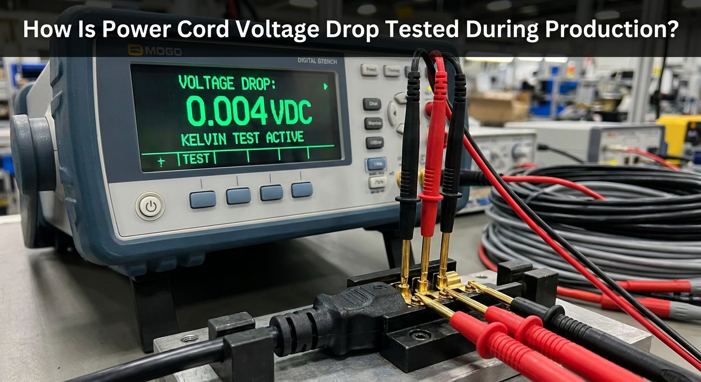
Power cord voltage drop is tested during production through automated quality control stations that apply a simulated load current and measure the precise differential voltage across the cable assembly. Quality assurance teams use high-precision digital multimeters and programmable DC electronic loads to verify that every manufactured assembly meets tight tolerance limits. Conducting rigorous, real-world testing ensures that no defective, high-resistance power cords reach end-users. Implementing robust testing protocols for power cord voltage drop is the only way to guarantee field-level reliability.
Modern factories integrate these automated checks directly into their assembly lines to screen out flawed units before packaging. These testing stations record electrical data in real time to trace production quality and identify potential systemic manufacturing issues. By analyzing this data, production managers can continuously refine their machinery and processes. This rigorous testing approach is vital for delivering zero-defect power solutions to global B2B clients.
What Equipment Is Used?
Modern factories utilize automated cable testers integrated with kelvin clip probes to perform four-terminal sensing, which eliminates probe lead resistance from measurements. Let’s face it: standard two-wire testing methods are too inaccurate to detect minor, yet critical, resistance anomalies in high-current cords. This advanced equipment ensures that every measurement reflects only the true resistance of the power cord under test. This high level of precision is necessary for maintaining strict quality standards.
To capture comprehensive performance data, quality control teams deploy a suite of specialized diagnostic tools. These devices work in tandem to audit cable assemblies:
- Four-Wire Kelvin Testers: Eliminates test lead resistance for high-accuracy checks.
- Programmable Electronic Loads: Simulates peak operating currents of target devices.
- Thermal Imaging Cameras: Identifies hot spots along the cord that indicate internal conductor damage.
How Are Limits Set?
Production lines set upper and lower threshold limits for acceptable voltage drops based on theoretical calculations and engineering margins. Any cable assembly that exceeds the maximum voltage drop limit is instantly flagged, sorted out, and subjected to destructive teardown analysis to isolate the root cause. This strict screening process prevents compromised cables from entering your supply chain. Maintaining tight testing limits is key to safeguarding product performance.
Key Takeaway: Professional factory testing with four-wire Kelvin probes is essential to identify marginal cables before they can cause field failures in your customer applications.
| Test Metric | Applied Current | Acceptable Range | Pass/Fail Action | |
|---|---|---|---|---|
| Contact Resistance | 1.0A | < 20 mΩ | Reject and discard. | |
| DC Voltage Drop | Rated Current (e.g., 3.0A) | < 150mV drop | Reject; route to teardown. | |
| Hi-Pot Insulation | 1500V AC | Zero leakage current | Immediate scrap. | |
| Thermal Profiling | 1.2x Rated Current | < 40°C rise | Flag for manual audit. |
Deploying four-wire Kelvin testing at full operational current is essential for screening out latent assembly defects that a simple continuity check would miss.
How Do You Select the Right Cable to Reduce Power Cord Voltage Drop?
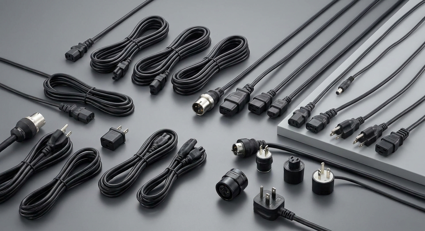
Selecting the right cable to reduce power cord voltage drop requires a systematic assessment of your device’s maximum current draw, the total distance to the power source, and environmental operating temperatures. By mapping these electrical parameters against standard AWG resistance tables, engineers can identify the optimal conductor size. Making the correct wire selection from the outset protects your equipment from under-voltage anomalies and ensures a highly reliable end-user experience. Proactive specification of appropriate wire sizes completely eliminates the risk of power cord voltage drop in your deployments.
Engineering teams should avoid using generic, under-specified power cords that do not match their system’s peak requirements. Investing in custom cable assemblies from a certified manufacturing partner ensures that your power path is designed for peak efficiency. This targeted selection process reduces electrical losses, lowers system heat, and guarantees stable operating voltages. Choosing the right cable is the final step in securing consistent, long-term product performance.
How Do You Size AWG?
Matching the wire gauge to your system’s peak current is the primary step in controlling voltage loss. Think about it: selecting a cable based on nominal average current rather than peak surge current is a recipe for system instability during heavy load cycles. High-draw devices will suffer from immediate voltage sags if the power path is not adequately sized. Sizing your conductors for peak conditions ensures that your hardware runs smoothly under all operating demands.
To simplify the selection process, engineers follow clear guidelines based on maximum current demands. Consider these standard power-to-wire pairings:
- Low Draw (Under 1A): Thin, highly flexible 24 AWG or 26 AWG wires are acceptable.
- Moderate Draw (1A to 3A): Standard 18 AWG to 20 AWG wires provide the best balance of cost and performance.
- High Draw (3A to 5A+): Heavy-duty 14 AWG to 16 AWG cables are mandatory to prevent severe voltage sag.
Does Temperature Matter?
Copper’s electrical resistance increases as temperature rises, which means that cables routed through hot industrial environments or sealed enclosures will exhibit significantly higher voltage drops. Selecting cables with high-temperature rated insulation prevents safety risks while maintaining low resistance. It is critical to account for these environmental factors during the early engineering phase of your project. Upgrading your wire size is highly recommended to offset both temperature-induced resistance and physical line losses.
Key Takeaway: Do not default to thin, generic power cords. Use a comprehensive sizing table to pair the correct AWG gauge with your maximum line length and current load.
| Target Voltage | Max Current Load | Recommended AWG (up to 2m) | Recommended AWG (up to 5m) | |
|---|---|---|---|---|
| 5.0V DC | 2.0A | 20 AWG | 16 AWG | |
| 12.0V DC | 3.0A | 18 AWG | 14 AWG | |
| 24.0V DC | 5.0A | 16 AWG | 12 AWG | |
| 110V AC | 10.0A | 14 AWG | 12 AWG |
Comparing these recommended pairings demonstrates how critical it is to scale up conductor thickness as current demands and cable lengths increase.
Conclusion
Overcoming the challenges of physical line resistance requires a strategic approach that combines precise calculations, careful material selection, and rigorous manufacturing standards. By identifying the root causes of electrical loss, understanding wire gauge limits, and applying strict testing methodologies, you can prevent system reboots and protect downstream electronics from undervoltage failure.
At Merryking, we specialize in addressing these exact performance challenges. Our state-of-the-art manufacturing facilities utilize pure oxygen-free copper conductors, advanced 4-wire Kelvin production line testing, and highly specialized line drop compensation modeling to deliver highly efficient, reliable power solutions worldwide. We are dedicated to ensuring your products receive stable, clean power in even the most challenging environments.
Ready to optimize your product’s power delivery and eliminate voltage drop issues? We invite you to contact us today to consult with our expert R&D engineering team and design a custom, high-compliance power adapter solution tailored to your exact application needs.
Frequently Asked Questions (FAQ)
Can I use a longer power cord without affecting performance?
No, you cannot do so without careful evaluation. Extending a power cord naturally increases the total electrical resistance of the circuit, which will lead to a higher voltage drop unless you simultaneously upgrade to a thicker wire gauge (lower AWG number).
What’s the best way to prevent voltage drop in long-distance runs?
Thicker copper conductors are the best choice. Increasing the wire gauge (such as stepping up from 22 AWG to 16 AWG) significantly lowers the cable’s resistance, keeping voltage drop well within the safe 3% threshold even over extended distances.
How do I know if my power cord is experiencing excessive voltage drop?
Measure the voltage under load to confirm. Using a digital multimeter, check the voltage output at the power source and then at the device’s input plug while the device is actively running under maximum load; a difference greater than 5% indicates an excessive and potentially harmful voltage drop.
Can I fix voltage drop issues by using a power adapter with higher output voltage?
Yes, you can do so within safe design limits. Many manufacturers use a slightly elevated nominal voltage (such as 5.1V instead of 5V) to pre-compensate for expected cable losses, but you must ensure the voltage does not exceed your device’s maximum rating when idling.
Can I ignore temperature when selecting a power cord?
No, you cannot. The electrical resistance of copper increases linearly with temperature, which means that a power cord operating in a hot environment or a sealed enclosure will naturally exhibit a greater voltage drop than one operating at standard room temperature.