Pull force testing is crucial for power adapters because it guarantees the physical durability of the cable connection, preventing electrical hazards and sudden product failures. Imagine a scenario where a user repeatedly yanks a charging cable from a wall outlet or trips over a cord stretched across a room. Over time, these daily stresses can easily pull the copper conductors out of their internal terminals, creating catastrophic short circuits, spark hazards, or costly product recalls that destroy your brand’s reputation. To prevent these dangerous failures, implementing a standardized power adapter pull force test provides a robust engineering solution that verifies structural integrity and secures ultimate user safety.
What Is a Power Adapter Pull Force Test?

A power adapter pull force test is a specialized mechanical evaluation that measures a cable assembly’s ability to withstand pulling tension without separating from the main housing. By subjecting the power cord to a specified linear force, this assessment ensures that the integrated strain relief sleeve successfully absorbs physical stress. When you implement a standardized power adapter pull force test , you can verify that mechanical strain never transfers to the sensitive internal electrical junctions. This process acts as a primary quality gate for ensuring long-term product durability.
What Are the Primary Test Goals?
What does this mean for you? You need to verify that your power supplies can handle extreme consumer handling without failing. The main objectives of this test include protecting internal components and maintaining housing integrity.
- Preventing internal solder joint breakage under high tension.
- Ensuring the outer cable jacket remains anchored securely inside the case.
- Eliminating the risk of exposed live copper wires.
You can rely on these parameters to build a highly durable and market-compliant power supply.
Which Key Metrics Must You Track?
Here is the key: you must monitor specific metrics during testing to ensure objective pass-fail decisions. These mechanical variables determine if your adapter design is truly robust.
- Tensile Strength: The peak linear force applied during evaluation.
- Displacement Limit: The maximum distance the cable jacket shifts.
- Torque Load: The rotational resistance at the cable entry point.
You must carefully document these values during every pre-production run to maintain quality control.
| Metric | Standard Unit | Common Target | Engineering Function | |
|---|---|---|---|---|
| Applied Pull Force | Newtons (N) | 30N to 100N | Simulates sudden yanking incidents | |
| Jacket Displacement | Millimeters (mm) | ≤ 2.0 mm | Measures longitudinal creepage under load | |
| Rotational Torque | Newton-meters (N-m) | 0.1 to 0.4 N-m | Evaluates twisting resistance at the joint |
The data in this table shows that maintaining a displacement of less than 2.0 mm under peak tension is essential for preventing internal electrical bridging.
Key Takeaway: By understanding and tracking these mechanical metrics, you can directly prevent physical strain from translating into hazardous electrical failure.
Why Is a Power Adapter Pull Force Test Important for Product Safety?
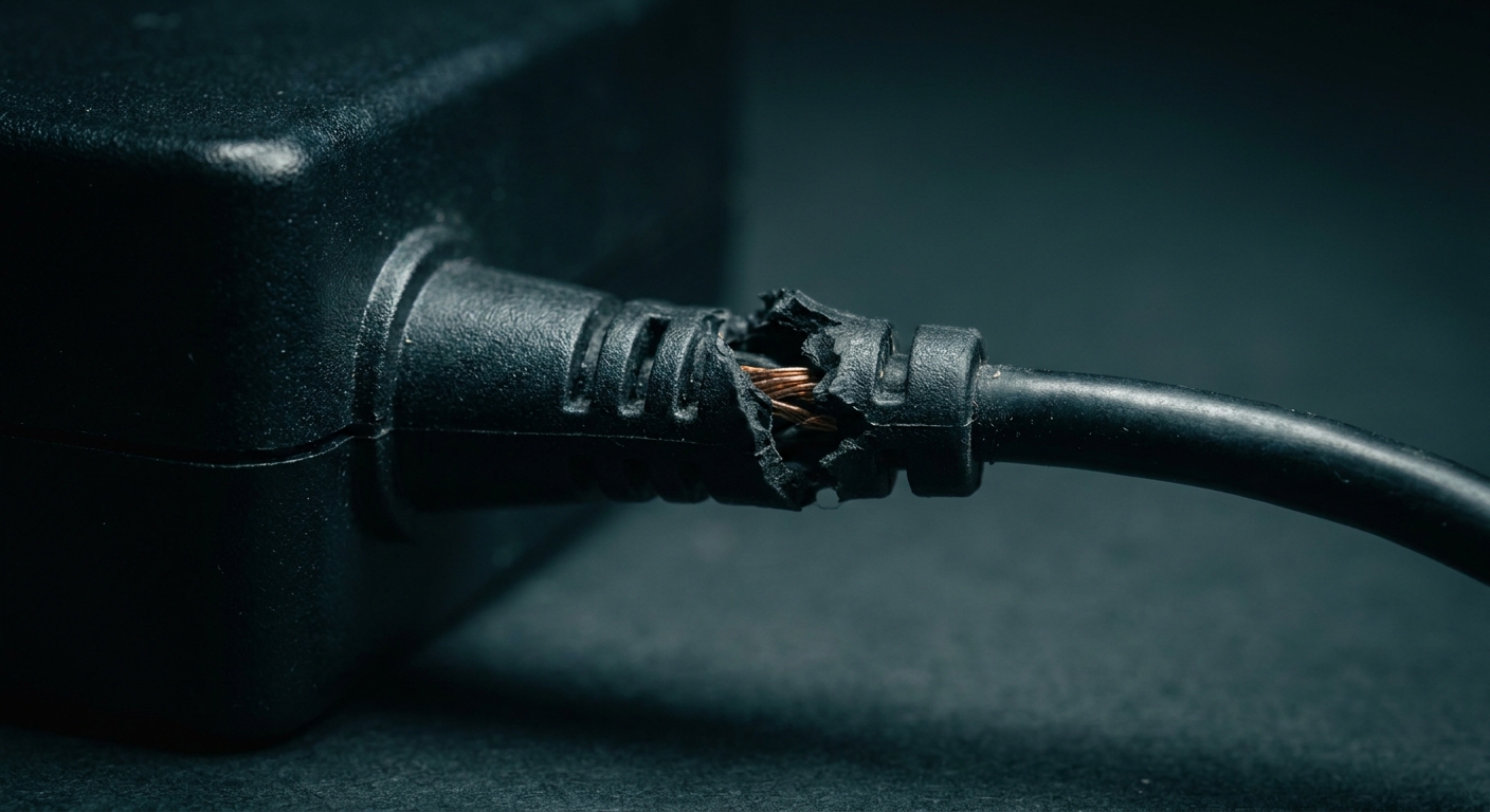
A power adapter pull force test is critical for product safety because it prevents damaged cables from exposing live electrical wires and causing lethal shocks or fires. Without this rigorous test, normal everyday handling can quickly compromise the cable’s physical barrier, creating hazardous conditions for your users. Implementing a continuous power adapter pull force test program ensures that every batch of power adapters meets strict safety thresholds before leaving the factory. This mechanical verification is your first line of defense against severe electrical accidents.
How Does It Prevent Electrical Shock?
Let’s face it: if the internal power conductors pull free from their terminals while connected to the mains, the risk of high-voltage exposure is immediate. You must design internal retention mechanisms that physically lock the cord in place.
- It blocks high-voltage arcs from jumping to low-voltage wires.
- It prevents bare copper strands from contacting the outer shell.
- It guarantees that the ground wire remains intact if applicable.
This safeguards your end customers from coming into contact with live hazardous currents.
How Does It Reduce Fire Risks?
Think about it. When copper wires inside a cable stretch or partially break due to tension, their electrical resistance skyrockets instantly.
- The localized resistance spike generates intense heat.
- Overheated insulation can melt and trigger a short circuit.
- Molten plastic can drop onto surrounding flammable materials.
You can prevent this dangerous thermal runaway by ensuring your cables never suffer internal conductor deformation.
| Hazard Category | Failure Mechanism | Preventive Design Strategy | |
|---|---|---|---|
| Electric Shock | Conductor detachment exposing live mains voltage | Mechanical clamping ribs inside the housing | |
| Thermal Fire | Stranded wire breakage leading to resistance spikes | Flexible overmolded strain relief transition | |
| Arcing Hazard | Intermittent connection at loose solder joints | Secure internal cable service loop |
This structured hazard mapping demonstrates that physical cable retention is directly tied to preventing hazardous electrical fires and shocks.
Key Takeaway: Prioritizing pull-force resistance ensures your power adapters remain completely safe for consumers, shielding your business from liability and costly recalls.
Which Components Are Evaluated in a Power Adapter Pull Force Test?
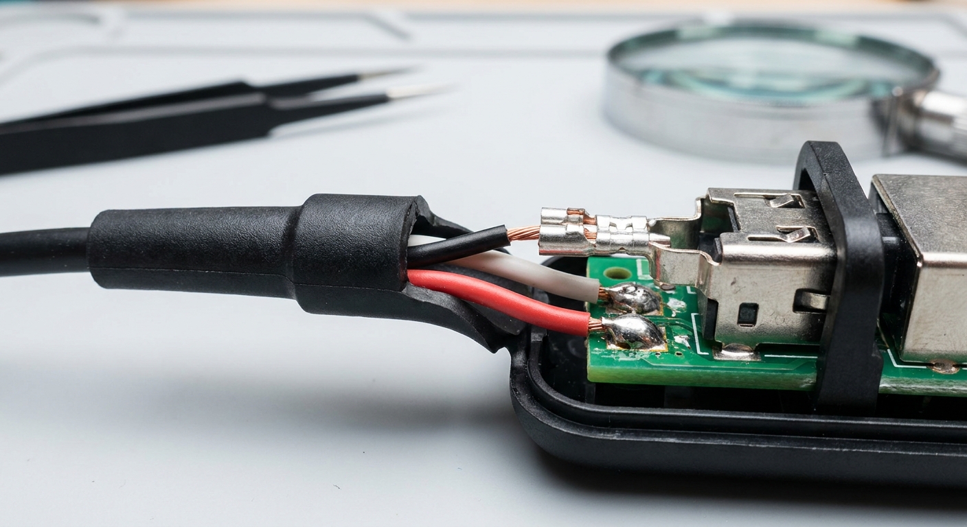
A power adapter pull force test evaluates the mechanical strength of the cable jacket, the strain relief sleeve, the internal clamping teeth, and the PCB solder terminals. Each of these interconnected components plays a vital role in keeping your power cord securely anchored to the main unit. Conducting a thorough power adapter pull force test allows you to pinpoint exactly which part of the cable assembly is the weakest link under tension. This targeted evaluation ensures that your desktop power adapter designs are robust enough for heavy daily use.
Why Focus on the Cable Jacket?
But that is not all. The outer cable jacket acts as the primary defense shield for the internal wiring, absorbing the brunt of all sliding and pulling forces.
- It must resist slipping backward through the housing entry hole.
- It needs high tear resistance to avoid cutting at the strain relief joint.
- It requires strict compatibility with internal mechanical clamp designs.
You must choose jacket materials that withstand high friction forces without tearing.
What Role Does Strain Relief Play?
Look closely at the mechanics: without a flexible strain relief sleeve, the cable would experience a sharp bend and high stress right at the enclosure’s exit.
- It distributes linear and bending forces over a longer area.
- It prevents localized stress concentrations on the copper strands.
- It protects the internal PCB solder pads from direct pull forces.
You can optimize this component’s length and thickness to match your adapter’s specific power rating.
| Component Evaluated | Mechanical Role | Target Quality Metric | |
|---|---|---|---|
| Outer Cable Jacket | Absorbs friction and protects inner conductors | Zero slip or tearing under tension | |
| Strain Relief Sleeve | Distributes bending and pulling stresses | High flexibility without cracking | |
| Internal Clamping Teeth | Physically locks the cable jacket inside housing | Strong mechanical grip without slicing |
This breakdown highlights that each component must work in perfect harmony to protect the delicate internal wiring from external forces.
Key Takeaway: Evaluating all these key physical components during your design phase ensures a robust cable assembly that can withstand real-world wear and tear.
How Is a Power Adapter Pull Force Test Performed?

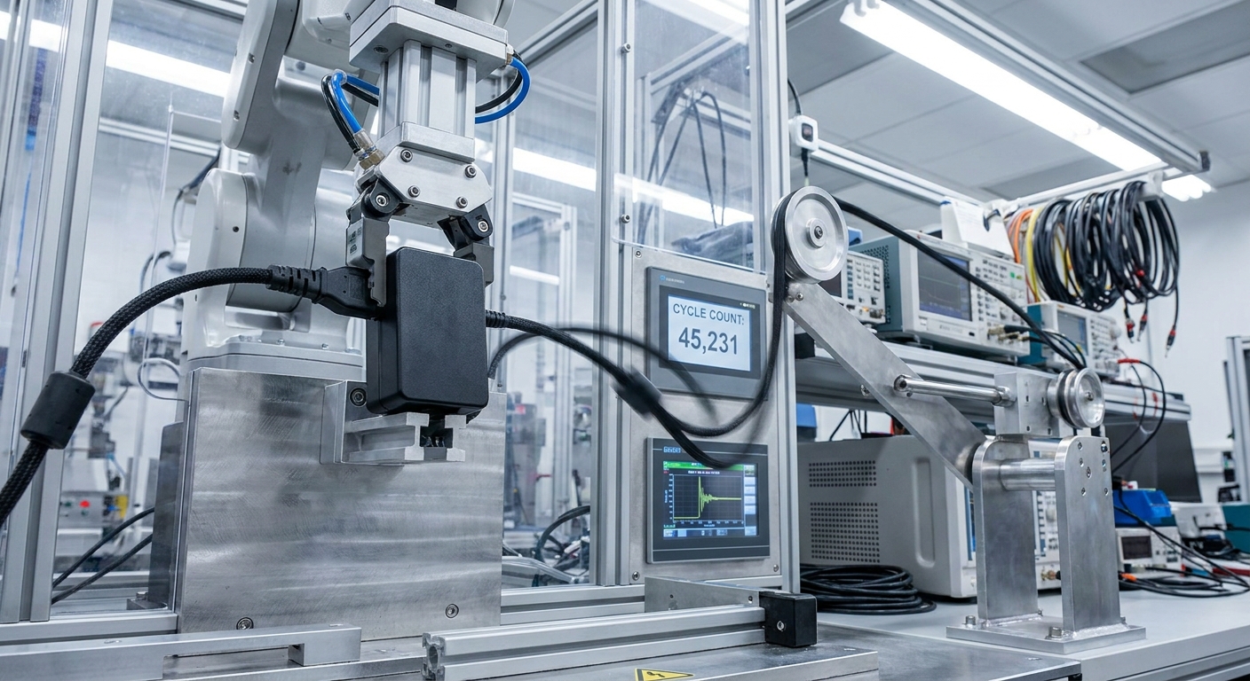
Performing a power adapter pull force test involves securing the adapter housing in a specialized fixture and applying a controlled, linear tension to the cable. This precise laboratory procedure ensures that the force is applied consistently and does not introduce sudden shock loads that could skew your results. Incorporating an automated power adapter pull force test in your quality control workflow allows you to accurately measure displacement and electrical continuity under load. This process ensures that your power supplies meet the exact performance requirements of international standards.
What Is the Testing Setup?
Do you want to know the secret to consistent testing? You must align the cable perfectly with the force sensor’s axis of pull to eliminate angular measurement errors.
- Secure the adapter body in a non-marring, custom-fit clamp.
- Attach the cable clamp at a specified distance from the strain relief.
- Zero the load cell to ensure accurate initial force readings.
This rigid alignment ensures that your data represents true mechanical limits.
What Are the Key Testing Steps?
What does this mean for you? You must follow a standardized sequence of force application to ensure compliance with strict safety audits.
- Apply a minor pre-load to remove any initial cable slack.
- Increase the tension slowly at a rate not exceeding 10N per second.
- Maintain the peak target force for the standard’s required dwell time.
- Inspect the cable for any signs of slippage, damage, or electrical failure.
This methodical approach guarantees highly repeatable data across all product batches.
| Test Phase | Operator Action | Key Variable to Control | |
|---|---|---|---|
| 1. Mounting | Lock adapter body in non-deforming fixture | Clamping pressure (prevent enclosure damage) | |
| 2. Tensioning | Increase load gradually to target (e.g., 40N/100N) | Force rate (keep under 10 Newtons per second) | |
| 3. Evaluation | Measure jacket movement and test electrical path | Displacement limits and visual jacket tears |
The sequential step-by-step protocol detailed above ensures that every power supply undergoes identical testing conditions for fair compliance reporting.
Key Takeaway: Standardizing your physical testing procedures ensures that all gathered performance data is reliable, accurate, and ready for regulatory compliance audits.
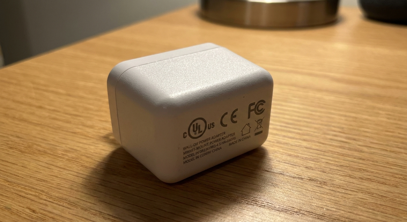
What Standards Apply to a Power Adapter Pull Force Test?
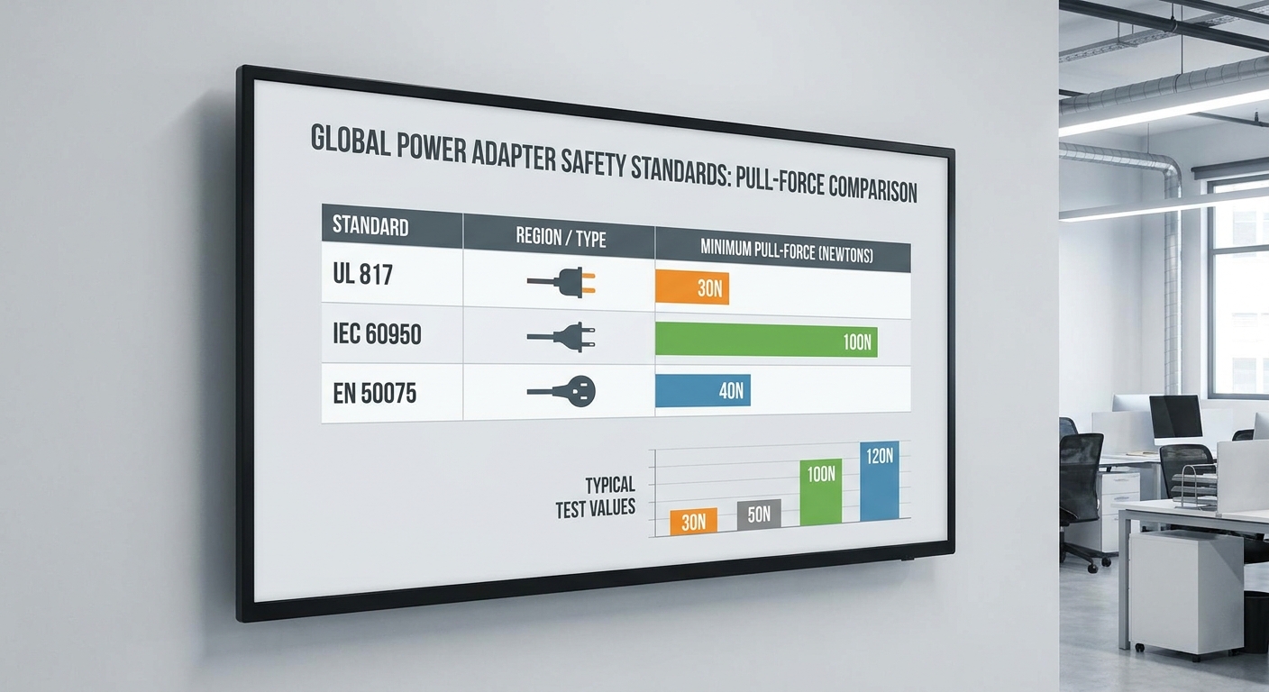
The primary international standards governing a power adapter pull force test include IEC 62368-1, IEC 60601-1, and UL 817. These strict regulatory guidelines define the exact physical forces, repetition counts, and torque loads that your devices must withstand to enter global markets. Ensuring your power adapter pull force test aligns with these standards is critical for passing third-party safety audits. By designing your wall-mount power adapter with these strict limits in mind, you can secure seamless entry into major regional markets.
What Does IEC 62368-1 Require?
Here is why: the modern IEC 62368-1 standard focuses on hazard-based safety engineering, making mechanical retention testing mandatory for almost all ICT and AV equipment.
- It requires a pulling force of either 40N or 100N depending on weight.
- The test must be repeated 25 times to simulate long-term fatigue.
- An immediate rotational torque test must be applied right after.
You must ensure your device shows zero damage and zero internal displacement after these cycles.
How Do Medical Standards Differ?
But that is not all. Medical electrical equipment must meet the incredibly strict IEC 60601-1 standard to ensure ultimate patient safety in clinical environments.
- It mandates a continuous 100N pull force for high reliability.
- A higher torque load is applied to ensure absolute twisting resistance.
- Zero electrical continuity interruption is allowed during testing.
You must design medical-grade power adapters with an extra safety margin to meet these demanding limits.
| Standard | Target Device Type | Pull Force (N) | Repetitions | Torque Load (N-m) | |
|---|---|---|---|---|---|
| IEC 62368-1 | AV & IT Equipment | 40 N / 100 N | 25 cycles | 0.1 N-m / 0.25 N-m | |
| IEC 60601-1 | Medical Equipment | 100 N | 25 cycles | 0.35 N-m | |
| UL 817 | Cord Assemblies | 133 N (30 lbs) | 1 minute (cont.) | N/A |
This compliance comparison indicates that medical and heavy-duty cord sets face much higher tension demands than basic office electronics.
Key Takeaway: Designing your power supplies to meet the strict limits of IEC 62368-1 and IEC 60601-1 guarantees hassle-free international certification and ensures broad market access.
How Does a Power Adapter Pull Force Test Improve Product Reliability?
A power adapter pull force test improves product reliability by identifying mechanical weak points under tension and verifying materials before mass production begins. By filtering out poor designs early in your engineering cycle, you can avoid costly field failures and expensive warranty claims. Regular execution of a power adapter pull force test on your assembly line ensures consistent quality and builds trust with your enterprise B2B customers. This predictive quality check directly translates to a lower product return rate and a much stronger market reputation.
Does It Reduce Warranty Costs?
Let’s face it: field failures due to broken power cords are highly frustrating for users and very expensive for your service department. You can significantly reduce these unnecessary overhead costs by verifying your strain relief’s durability beforehand.
- It lowers the frequency of customer service tickets for power issues.
- It decreases the need for shipping expensive replacement power bricks.
- It avoids negative online reviews that hurt future sales.
What does this mean for you? You save valuable operational capital while boosting overall customer satisfaction.
How Does It Ensure Material Quality?
Think about it. Even minor changes in your raw plastic or rubber formulations can dramatically impact how your cable strain relief performs under stress.
- It verifies that your supplier’s plastic compound meets hardness specs.
- It catches issues like brittle PVC batches before they reach assembly.
- It ensures the overmolded elastomer bonds perfectly with the wire jacket.
You can use this physical test as an incoming inspection filter to hold your raw material suppliers fully accountable.
| Reliability Benefit | Engineering Impact | Business Outcome | |
|---|---|---|---|
| Lower RMA Rates | Fewer physical cable separations | Drastically reduced warranty replacement costs | |
| Consistent Materials | Catches brittle raw plastic batches | High batch-to-batch consistency on assembly lines | |
| Enhanced Trust | Adapters last throughout the device’s lifespan | Stronger brand reputation and repeat B2B orders |
This business-impact analysis shows that investing in rigorous mechanical testing directly supports long-term customer retention and healthy profit margins.
Key Takeaway: Incorporating mechanical reliability testing into your development cycle protects your brand from the financial and reputational fallout of early cable failures.
What Common Failures Are Found During a Power Adapter Pull Force Test?
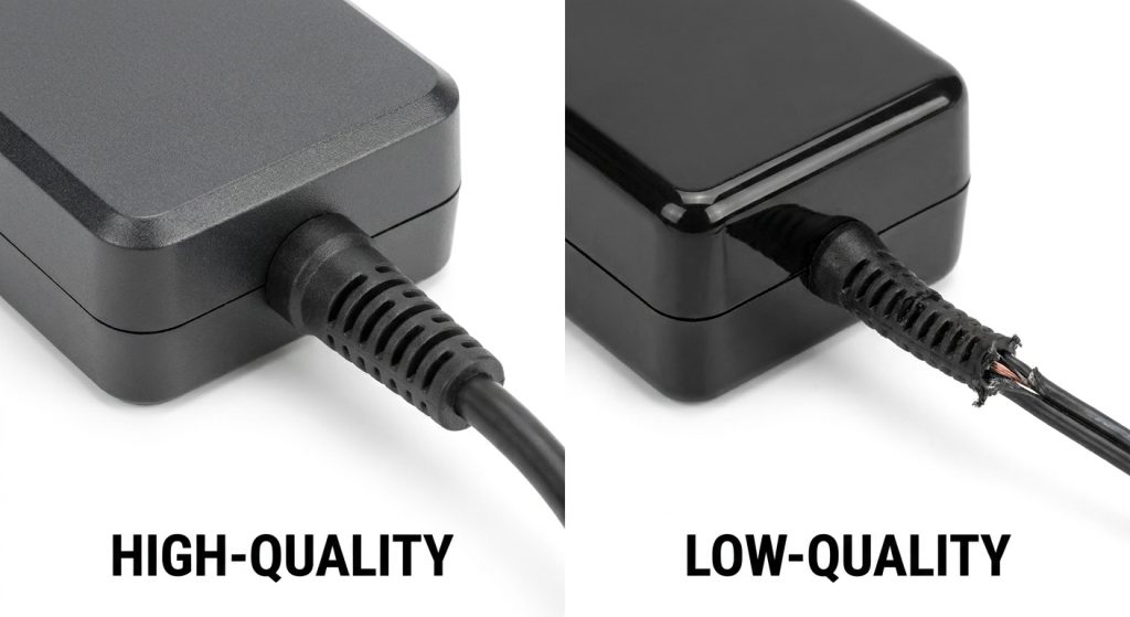
Common failures found during a power adapter pull force test include cable jacket slippage, torn overmolding, broken copper conductors, and fractured PCB solder joints. These mechanical breakdowns occur when the physical forces applied to the cable bypass your strain relief and act directly on fragile internal structures. Utilizing a detailed power adapter pull force test helps you identify these failure modes before your USB-C power adapter is released to the market. Understanding these common failure points is the key to engineering a highly resilient power supply.
Why Does Cable Slip Happen?
Here is why: if your housing’s internal clamping teeth do not compress the cable jacket with enough force, the wire will slide out easily under tension.
- Insufficient depth of the internal plastic retaining ribs.
- Excessive tolerance variations in the cable’s outer diameter.
- Poor friction characteristics of the chosen jacket material.
You must ensure that your enclosure halves provide optimal mechanical compression when ultrasonic welding is complete.
What Causes Internal Wire Breakage?
The danger is real: when the internal copper wires are pulled taut inside the housing without any slack, even minor external pulls can snap the connections.
- Lack of an internal service loop to absorb small movements.
- Direct solder joint loading due to weak mechanical anchors.
- Brittle solder alloy selection that easily cracks under stress.
What does this mean for you? You must design an internal wire routing path that prevents physical stress from ever reaching the electronic terminals.
| Common Failure Mode | Physical Root Cause | Target Design Solution | |
|---|---|---|---|
| Jacket Pull-Out | Weak internal clamping ribs inside housing | Add sharp interlocking retention teeth | |
| Conductor Shear | Tension applied to taut internal copper strands | Introduce a loose S-shaped internal service loop | |
| Overmold Tearing | Brittle strain relief material or sharp edges | Specify high-tear-strength elastomer compounds |
This table provides a direct roadmap for transforming typical mechanical weaknesses into highly robust design features.
Key Takeaway: By proactively eliminating these common mechanical failure points, you can design a power adapter that easily breezes through safety agency certifications.
How Does a Power Adapter Pull Force Test Help Prevent Cable Damage?
A power adapter pull force test prevents cable damage by verifying that the strain relief sleeve effectively absorbs linear tension and distributes bending stresses. This diagnostic check ensures that everyday physical wear does not lead to localized tearing or catastrophic wire fatigue. Regularly subjecting your designs to a power adapter pull force test allows you to optimize the physical transition between the flexible cord and the rigid adapter shell. This preventive approach keeps your power supplies physically intact even under extreme consumer handling conditions.
How Does It Optimize Bend Relief?
Do you want to know the secret to extending your cable’s lifespan? You must design a graduated strain relief sleeve that distributes the stress over a larger radius.
- It prevents a sharp 90-degree kink at the adapter housing exit.
- It reduces local strain on the outer insulation jacket.
- It helps the cable bounce back easily after heavy flexing.
This mechanical optimization keeps the copper conductors inside from suffering fatigue and breaking prematurely.
How Does It Prevent Jacket Tearing?
Let’s face it: a torn cable jacket not only looks bad but also exposes the internal wires to moisture, dust, and potential short circuits.
- It forces you to evaluate the tear strength of your overmold compounds.
- It ensures the plastic housing exit hole has radiused, non-sharp edges.
- It checks the bond quality between the overmold and the wire insulation.
You can easily avoid these mechanical defects by adjusting your tooling dimensions and material parameters.
| Damage Prevented | Mechanical Root Cause | Validation Benefit | |
|---|---|---|---|
| Sharp Cable Kinking | Lack of graduated bend transition | Keeps bend radius broad, protecting internal copper | |
| Insulation Splits | Sharp plastic housing exit edges | Verifies that exit hole radii are sufficiently rounded | |
| Outer Sleeve Separation | Weak adhesion between overmold and cable | Confirms a secure chemical fuse during injection |
Focusing on these critical transition points ensures that physical wear is absorbed by robust elastomer surfaces rather than thin insulating layers.
Key Takeaway: Designing with a focus on strain-relief mechanics prevents external force concentration, ensuring your power cables remain intact and operational for years.
What Equipment Is Used for a Power Adapter Pull Force Test?
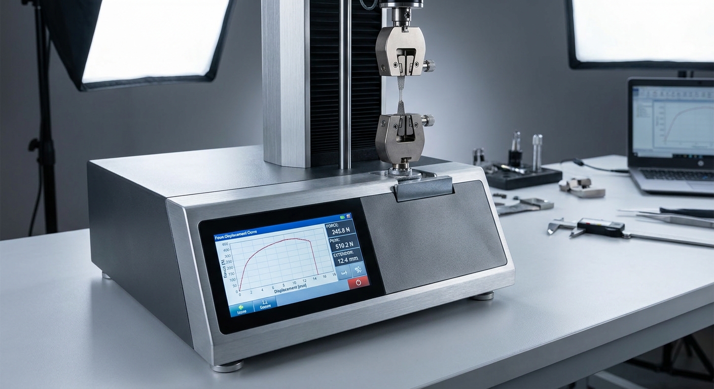
A power adapter pull force test requires high-precision testing equipment, including motorized tensile testing stands, digital force gauges, and specialized pneumatic clamping fixtures. These specialized tools ensure that the applied tension is completely linear and free from manual errors. Utilizing calibrated machinery for your power adapter pull force test provides traceable, repeatable data that stands up to strict safety audits. Investing in the right laboratory equipment is crucial for verifying that your wall-mount power adapter meets international safety guidelines.
Why Use Motorized Test Stands?
Think about it: why are manual pull tests using spring scales or hanging weights generally unacceptable for official compliance reports?
- Manual pulling introduces sudden, uncontrollable shock loads.
- Hanging weights can bounce, causing a false spike in applied tension.
- Motorized stands maintain a constant speed of under 10N per second.
You need this precision motorized control to gather stable, repeatable mechanical compliance data.
What Role Does Software Play?
But that is not all. Modern test stations integrate advanced software systems that capture high-resolution real-time load vs. displacement curves.
- It visually displays the elastic and plastic deformation limits.
- It instantly flags any sample that exceeds the maximum displacement.
- It generates traceable, audit-ready compliance PDF reports.
You can use these automated logs to easily prove your factory-level QC consistency to high-profile B2B clients.
| Equipment Tool | Key Technical Feature | Role in Compliance Testing | |
|---|---|---|---|
| Motorized Test Stand | Speed-regulated linear actuator | Applies force smoothly without sudden shock loads | |
| Digital Force Gauge | S-type load cell with high sampling rate | Captures peak tension forces with 0.1N resolution | |
| Pneumatic Grippers | Adjustable constant pressure clamps | Grips the cable securely without slicing the jacket |
This array of specialized equipment shows that capturing accurate, repeatable compliance data requires eliminating human measurement variables.
Key Takeaway: Partnering with a manufacturer equipped with automated digital testing stands guarantees that your product validation reports are accurate and legally defensible.
How Can Manufacturers Pass a Power Adapter Pull Force Test Consistently?

Manufacturers can pass a power adapter pull force test consistently by integrating robust interlocking internal clamps, using high-tear-strength overmold compounds, and keeping a loose wire service loop. These physical design choices prevent external forces from ever reaching the delicate internal printed circuit board joints. Standardizing these techniques in your manufacturing process ensures that every power adapter pull force test on your production line achieves a perfect score. By partnering with a pre-certified, experienced OEM manufacturer, you can guarantee that your power supplies easily pass safety audits.
Why Design an Internal Service Loop?
Here is the key: you must ensure that the internal copper wires are never under tension inside the plastic adapter housing.
- Always route the internal wires with a loose, S-shaped bend.
- Ensure the physical outer jacket clamp absorbs 100% of the pull force.
- Prevent any micro-displacement from stressing the solder pads.
This simple wire-routing design choice virtually eliminates the risk of internal joint failure during testing.
What Materials Are Best?
What does this mean for you? You must choose strain relief overmolding materials that provide the optimal balance of elasticity and shear resistance.
- TPE: Offers excellent fatigue resistance and elastic recovery.
- TPU: High-end choice with premium tear strength and robust wear limits.
- PVC: Budget-friendly option suitable for standard light-duty consumer electronics.
You can consult with your manufacturing partner to select the ideal compound for your specific target market.
| Development Phase | Recommended Action | Design Validation Step | |
|---|---|---|---|
| Concept & CAD | Add internal interlocking clamping teeth | Finite Element Analysis (FEA) modeling of stress zones | |
| Prototyping | Verify raw overmolding material bonding | Mock sample pull testing to determine peak limits | |
| Mass Production | Set up automated, calibrated test stands | Daily random batch testing of 50 units for QC logging |
This phase-by-phase execution strategy ensures that mechanical safety is built into the product from day one rather than patched later.
Key Takeaway: Prioritizing mechanical safety and partner expertise in the design stage is the single most effective way to pass global safety compliance tests consistently.
Securing Ultimate Reliability with Certified Power Solutions
Designing a high-performance power adapter is about much more than electrical schematics; it requires building a physically resilient product that can withstand the daily rigors of real-world use. When you ignore mechanical safety procedures like pull force testing, you open your business to severe product safety hazards, expensive recalls, and damaged customer trust. By implementing robust mechanical designs, choosing premium overmold materials like TPU, and utilizing automated testing stands, you can guarantee safety compliance and exceptional product longevity.
At Merryking Power, we have over 20 years of direct manufacturing expertise, offering a complete range of pre-certified wall-mount, desktop, and interchangeable-plug power adapters. Our state-of-the-art Dongguan facility handles everything from initial custom CAD design to rigorous automated quality control, ensuring your products easily pass global safety reviews on the first attempt. If you want to elevate your power supply quality and protect your brand’s reputation, contact our team to schedule a consultation and request factory-direct samples today.
FAQ
Can I perform a pull force test without specialized laboratory equipment?
No, manual testing with simple spring scales or weights does not meet official certification standards. Motorized test stands are required to maintain a constant, steady pull rate of under 10N per second to avoid artificial shock-loading.
What’s the best material for overmolding to pass the pull force test?
Absolutely, Thermoplastic Polyurethane (TPU) is the premium choice for high-durability strain relief overmolding. TPU offers exceptional tear resistance, high shear strength, and chemically fuses to the cable’s outer jacket during the overmolding process.
How do I calculate the specific pull force required for my adapter?
Yes, you can calculate this by consulting the specific safety standard (like IEC 62368-1) that matches your device class, weight, and operating voltage. For example, most mains-powered consumer IT adapters must withstand either a 40N or a 100N pulling force.
Is a torque test always required alongside the pull force test?
Yes, most global safety standards (including UL and IEC) require an immediate rotational torque test following the linear pulling test. This ensures that the strain relief sleeve prevents both axial pull-out and twisting forces that could shear internal conductors.
Why does the internal copper wire break before the outer jacket fails?
Yes, this occurs when the internal wiring lacks a proper slack service loop, causing the copper conductors to be tighter than the outer jacket. When tension is applied, the physical stress bypasses the outer jacket clamps and acts directly on the delicate wire strands, causing them to snap.